Pipefitting is a trade where a small math mistake can turn into a big field problem. A wrong takeoff, missed centerline dimension, incorrect rolling offset, or bad degree calculation can mean cutting out work that was already welded, wasting fittings, or losing hours of production.
The good news is that most pipefitter math comes back to a relatively small group of formulas.
This guide covers 50 calculations every pipefitter should know, from basic fractions and circumference to offsets, rolling offsets, fitting takeoffs, bolt circles, slopes, and fabrication calculations.
Keep in mind that field dimensions, fitting dimensions, tolerances, codes, manufacturer data, drawings, and project specifications always take priority over generalized formulas or rules of thumb.
1. Fraction to Decimal
Pipe dimensions are often given as fractions, while calculators and fabrication software commonly use decimals.
Formula:
Decimal = Numerator ÷ Denominator
Example:
3/8 = 3 ÷ 8 = 0.375
Common conversions:
• 1/8 = 0.125
• 1/4 = 0.250
• 3/8 = 0.375
• 1/2 = 0.500
• 5/8 = 0.625
• 3/4 = 0.750
• 7/8 = 0.875
2. Decimal to Fraction
To convert a decimal inch measurement back into a fraction, multiply the decimal by the denominator you want to use.
Example:
0.625 × 8 = 5
Therefore:
0.625 = 5/8 in.
3. Adding Fractions
Fractions must have a common denominator before they can be added.
Example:
3/8 + 1/4
Convert 1/4 to 2/8:
3/8 + 2/8 = 5/8
4. Subtracting Fractions
The same principle applies when subtracting.
Example:
7/8 − 1/4
1/4 = 2/8
7/8 − 2/8 = 5/8
5. Feet and Inches to Decimal Feet
This calculation is useful for elevations, layout, total runs, estimating, and surveying.
Formula:
Decimal Feet = Feet + (Inches ÷ 12)
Example:
8 ft 6 in.
8 + (6 ÷ 12) = 8.5 ft
6. Decimal Feet to Feet and Inches
Take the decimal portion and multiply it by 12.
Example:
12.75 ft
0.75 × 12 = 9 in.
Therefore:
12.75 ft = 12 ft 9 in.
PIPE GEOMETRY
7. Pipe Circumference
Circumference is the distance around a circle.
Formula:
C = π × D
Where:
C = circumference
D = diameter
π ≈ 3.1416
Example:
For a 10-inch diameter:
C = 3.1416 × 10
C = 31.416 in.
8. Finding Diameter From Circumference
Reverse the circumference formula.
Formula:
D = C ÷ π
If the measured circumference is 37.70 inches:
37.70 ÷ 3.1416 ≈ 12 in.
9. Radius
Radius is half the diameter.
Formula:
R = D ÷ 2
A 12-inch diameter circle has a radius of:
12 ÷ 2 = 6 in.
10. Area of a Circle
Formula:
A = πr²
For a circle with a 4-inch radius:
A = 3.1416 × 4²
A ≈ 50.27 in²
11. Cross-Sectional Flow Area
When using the actual inside diameter of a pipe:
Formula:
A = π × ID² ÷ 4
If the ID is 6 inches:
A = 3.1416 × 36 ÷ 4
A ≈ 28.27 in²
Always use the actual ID when accuracy matters. Nominal pipe size is not necessarily the inside diameter.
12. Pipe Volume
Once the internal cross-sectional area is known:
Formula:
V = A × L
Make sure the area and length use compatible units.
This calculation is useful when estimating internal volume for hydrotesting, flushing, chemical cleaning, or process calculations.
RIGHT TRIANGLE MATH
A huge amount of pipefitter layout is right-triangle geometry.
13. Pythagorean Theorem
Formula:
a² + b² = c²
Where c is the hypotenuse.
If:
a = 3 ft
b = 4 ft
Then:
c = √(3² + 4²)
c = 5 ft
14. Finding a Missing Leg
If the hypotenuse and one leg are known:
Formula:
a = √(c² − b²)
Example:
c = 13
b = 5
a = √(169 − 25)
a = √144
a = 12
15. 3-4-5 Square
The 3-4-5 method is one of the fastest ways to establish a 90° angle.
Measure:
3 units on one direction
4 units on the other direction
The diagonal should measure:
5 units
The ratio can be scaled:
6-8-10
9-12-15
12-16-20
The larger the layout, the easier it can be to detect small errors.
OFFSET CALCULATIONS
16. 45° Offset Travel
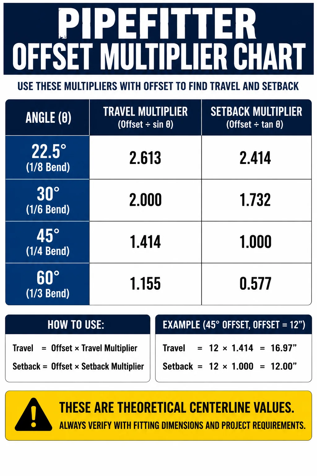
For a simple 45° offset:
Formula:
Travel = Offset × 1.414
Example:
Offset = 12 in.
12 × 1.414 = 16.97 in.
Approximately 16 31/32 in.
17. 45° Offset Setback
For a theoretical 45° centerline offset:
Setback = Offset
A 12-inch offset therefore has a theoretical 12-inch setback.
Actual fabrication dimensions must account for fitting geometry and takeoffs.
18. 30° Offset Travel
Formula:
Travel = Offset × 2
For a 10-inch offset:
10 × 2 = 20 in.
19. 30° Offset Setback
Formula:
Setback = Offset × 1.732
For a 10-inch offset:
10 × 1.732 = 17.32 in.
20. 60° Offset Travel
Formula:
Travel = Offset × 1.155
For a 10-inch offset:
10 × 1.155 = 11.55 in.
21. 60° Offset Setback
Formula:
Setback = Offset × 0.577
For a 10-inch offset:
10 × 0.577 = 5.77 in.
22. Any-Angle Offset Travel
You do not need to memorize every possible angle.
Formula:
Travel = Offset ÷ sin(θ)
Where θ is the fitting angle.
This allows the travel to be calculated for virtually any offset angle.
23. Any-Angle Setback
Formula:
Setback = Offset ÷ tan(θ)
This gives the theoretical centerline setback.
ROLLING OFFSETS
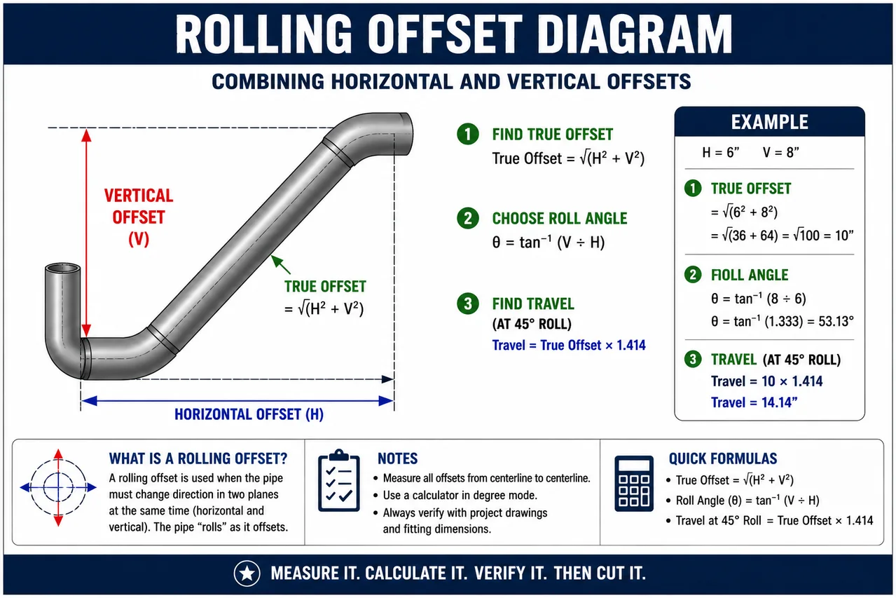
A rolling offset occurs when the pipe must move in two perpendicular directions at the same time—for example, horizontally and vertically.
24. True Offset
First combine the two offsets.
Formula:
True Offset = √(Horizontal² + Vertical²)
Example:
Horizontal = 6 in.
Vertical = 8 in.
True Offset = √(6² + 8²)
= √100
= 10 in.
25. 45° Rolling Offset Travel
Once the true offset is known:
Formula:
Travel = True Offset × 1.414
Using the previous 10-inch true offset:
10 × 1.414 = 14.14 in.
26. Rolling Offset Direction Angle
The direction of the roll can be calculated using:
Formula:
θ = tan⁻¹(Vertical ÷ Horizontal)
For:
Vertical = 8
Horizontal = 6
θ ≈ 53.13°
This angle describes the direction of the roll when viewed in the plane of the two offsets.
FITTING TAKEOFFS
27. 90° Elbow Center-to-End
For a standard 90° elbow, the center-to-end dimension depends on the fitting standard, size, radius designation, and manufacturer.
For ASME long-radius elbows, the nominal centerline radius is commonly:
R = 1.5 × NPS
For a 6-inch LR elbow:
R = 1.5 × 6 = 9 in.
Verify actual fitting dimensions before fabrication.
28. Short-Radius 90° Elbow
For an ASME short-radius 90° elbow, the nominal centerline radius is commonly:
R = 1 × NPS
For a 6-inch SR elbow:
R = 6 in.
Again, fitting standards and actual dimensions control.
29. 45° Elbow Takeoff
Do not assume the center-to-end dimension of a manufactured 45° elbow can always be calculated simply from the nominal elbow radius.
Use the applicable fitting dimensional standard, project table, or manufacturer data for the actual 45° center-to-end dimension.
This distinction prevents one of the easiest fitting-layout mistakes to make.
30. Straight Piece Between Two 90s
For a simple center-to-center spool:
Formula:
Cut Length = Center-to-Center − Takeoff 1 − Takeoff 2
Example:
Center-to-center = 48 in.
Each elbow takeoff = 9 in.
48 − 9 − 9 = 30 in.
Any weld gaps or fabrication allowances must then be handled according to the actual joint configuration and shop procedure.
31. Straight Piece Between Fittings
The same principle works for many fitting combinations.
Formula:
Cut Length = Required Centerline Dimension − Fitting Takeoffs
Identify what each drawing dimension references before subtracting anything.
32. Face-to-Face Spool Length
If the required dimension is flange face to flange face, the pipe cut length depends on the flange type and joint configuration.
Conceptually:
Pipe Cut Length = Required Face-to-Face − End Allowances
Those allowances may include flange dimensions, socket depths, weld gaps, or other fabrication requirements.
Never use one universal flange deduction for every flange type.
ANGLES AND DEGREE LAYOUT
33. Degrees Around a Circle
A full circle contains:
360°
Half:
180°
Quarter:
90°
Eighth:
45°
This becomes important for fitting orientation, flange layout, pipe marking, and fabrication.
34. Degrees Per Equal Division
Formula:
Degrees per Division = 360° ÷ Number of Divisions
For eight equal divisions:
360 ÷ 8 = 45°
35. Circumference Distance Per Degree
Formula:
Distance per Degree = Circumference ÷ 360
If circumference is 36 inches:
36 ÷ 360 = 0.1 in. per degree
36. Arc Length
Formula:
Arc Length = Circumference × (Angle ÷ 360)
For a 24-inch circumference and a 90° arc:
24 × 90/360 = 6 in.
SLOPE AND GRADE
37. Slope per Foot
If a line must fall 1/4 inch per foot:
Formula:
Total Fall = Length in Feet × 1/4 in.
For 20 ft:
20 × 0.25 = 5 in.
38. Percent Slope
Formula:
Slope % = Rise or Fall ÷ Horizontal Run × 100
If a line drops 1 ft over 100 ft:
1 ÷ 100 × 100 = 1%
39. Convert Percent Grade to Fall per Foot
Formula:
Fall per Foot = Grade Decimal × 12
For a 2% grade:
0.02 × 12 = 0.24 in./ft
That is close to 1/4 inch per foot, but it is not exactly the same.
MITER AND FABRICATION MATH
40. Equal Miter Cut Angle
For two equal pieces forming a change in direction:
Formula:
Miter Angle = Included Direction Change ÷ 2
For a 90° corner:
90 ÷ 2 = 45° per piece
This simple rule applies to two-piece equal miters; segmented pipe bends require additional layout calculations.
41. Chord Length
A chord is the straight-line distance between two points on a circle.
Formula:
Chord = 2R × sin(θ/2)
Where θ is the included central angle.
Useful for circular layouts and fabrication.
42. Arc Length From Radius
Another way to calculate arc length:
Formula:
Arc Length = 2πR × (θ ÷ 360)
FLANGE AND BOLT LAYOUT
43. Bolt Hole Spacing Angle
For equally spaced bolt holes:
Formula:
Angle = 360° ÷ Number of Bolt Holes
For an 8-hole flange:
360 ÷ 8 = 45°
44. Adjacent Bolt-Hole Chord
If bolt circle diameter and number of holes are known:
Formula:
Chord = BCD × sin(180° ÷ N)
Where:
BCD = bolt circle diameter
N = number of equally spaced holes
This gives the straight-line center-to-center distance between adjacent bolt holes.
45. Bolt Circle Radius
Formula:
Radius = Bolt Circle Diameter ÷ 2
A 12-inch bolt circle has a radius of:
6 in.
WEIGHT, VOLUME AND FIELD ESTIMATING
46. Pipe Weight
If pipe weight per foot is known:
Formula:
Total Weight = Weight per Foot × Length
Example:
18.97 lb/ft × 20 ft = 379.4 lb
Use verified pipe data for the actual NPS, schedule, and material.
47. Water Weight Inside Pipe
Once internal volume is known, water weight can be estimated using:
Water Weight = Volume × Water Density
At typical conditions, water weighs approximately:
8.34 lb per U.S. gallon
This matters during hydrotesting and when considering temporary loads and supports.
48. Gallons in a Pipe
Using an inside diameter measured in inches and pipe length measured in feet:
Approximate Formula:
Gallons = ID² × Length × 0.0408
Example:
6-inch ID × 20 ft
6² × 20 × 0.0408
≈ 29.4 gallons
Use actual inside diameter when accuracy matters.
FIELD LAYOUT
49. Centerline Elevation
If the bottom-of-pipe elevation and actual outside diameter are known:
Formula:
Centerline Elevation = BOP Elevation + OD/2
For top-of-pipe:
Centerline Elevation = TOP Elevation − OD/2
Use actual OD, not nominal pipe size.
50. Pipe-to-Pipe Centerline Spacing
If two pipes require a specified clear gap:
Formula:
Centerline Spacing = R₁ + R₂ + Required Clearance
Example:
Pipe A OD = 10.75 in.
Pipe B OD = 6.625 in.
Required clear space = 3 in.
R₁ = 5.375 in.
R₂ = 3.3125 in.
Centerline spacing:
5.375 + 3.3125 + 3
= 11.6875 in.
or approximately 11 11/16 in.
Quick Pipefitter Formula Reference
Circumference
C = πD
Circle Area
A = πr²
Pythagorean Theorem
a² + b² = c²
45° Offset Travel
Travel = Offset × 1.414
30° Offset Travel
Travel = Offset × 2
60° Offset Travel
Travel = Offset × 1.155
Any-Angle Travel
Travel = Offset ÷ sin(θ)
Any-Angle Setback
Setback = Offset ÷ tan(θ)
Rolling True Offset
True Offset = √(Horizontal² + Vertical²)
Rolling Travel at 45°
Travel = True Offset × 1.414
Arc Length
Arc = πD × Angle/360
Slope Percentage
Slope % = Rise or Fall ÷ Run × 100
Bolt Spacing Angle
360° ÷ Number of Holes
Adjacent Bolt-Hole Chord
Chord = BCD × sin(180°/N)
Pipe Volume
Volume = Internal Area × Length
Centerline Spacing
CL = R₁ + R₂ + Clearance
Final Word
A pipefitter does not need to be a mathematician.
But a good pipefitter needs to understand what the numbers represent.
The formulas matter because they allow you to turn dimensions on paper into pipe that actually fits in the field. Fractions, triangles, offsets, fitting takeoffs, elevations, slopes, bolt circles, and centerlines are all different versions of the same basic skill: understanding geometry well enough to build accurately.
Memorize the calculations you use constantly. Know how to derive the ones you forget. And when fitting dimensions, tolerances, manufacturer specifications, engineered drawings, or project requirements are available, verify the math against them before cutting pipe.
Measure it. Calculate it. Verify it. Then cut it.
Næxon Learning Center — Built for the people who build America.


