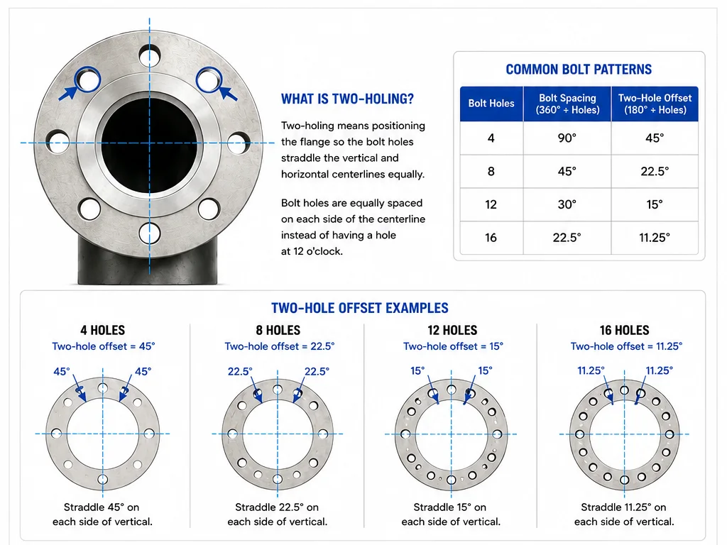
Two-holing a flange normally means positioning it so that the bolt holes are straddling the vertical and horizontal centerlines correctly, rather than having a bolt hole sitting directly at 12 o’clock.
Flange pins make that fast.
But what if you don’t have flange pins?
You can still two-hole a flange accurately using basic layout tools such as a level, straightedge, bolts, combination square, tape, wraparound, or even temporary hardware already available in the field.
The key is understanding what “two-hole” actually means geometrically.
What Does Two-Holing a Flange Mean?
When a flange is properly two-holed, the bolt-hole pattern is rotated so the holes are equally spaced on either side of the vertical centerline.
Imagine looking directly at the flange face.
Instead of:
One bolt hole at 12 o’clock
you want:
Two bolt holes equally spaced around 12 o’clock
The same relationship occurs at 3, 6, and 9 o’clock.
For a standard evenly spaced bolt pattern, the amount of rotation depends on the number of bolt holes.
If the bolt-hole spacing is:
360° ÷ Number of Bolt Holes
then the two-hole rotation from a hole-on-center position is half of that:
Two-hole offset = 180° ÷ Number of Bolt Holes
Example:
For an 8-hole flange:
180 ÷ 8 = 22.5°
So an 8-hole flange that is properly two-holed has the nearest holes approximately 22.5° on either side of vertical.
Why Flanges Are Two-Holed
Two-holing creates a consistent bolt-hole orientation.
That matters during fabrication, installation and equipment connection because piping drawings and flange standards commonly assume consistent orientation unless the drawing specifically calls for something different.
It also helps:
- Maintain consistent spool orientation
- Match mating flanges
- Simplify field installation
- Prevent accidental flange clocking errors
- Keep fabricated piping consistent with drawings
That consistency becomes especially important on large piping systems where a single incorrectly clocked flange can create substantial rework.
Method 1: Use Two Bolts and a Level
This is one of the simplest field methods.
You need:
Two bolts
A level
Install two bolts into bolt holes that are positioned across the top of the flange.
Do not tighten them.
The bolts become temporary extensions of the hole centers.
Lay the level across the two bolts.
Rotate the flange until the level reads perfectly level.
If those two bolt holes are the correct pair straddling the vertical centerline, the flange is now two-holed.
This works because both bolt centers are at the same elevation when the bolt pattern is properly oriented.
Basic sequence
- Insert two bolts into the appropriate top holes.
- Place the level across the bolts.
- Rotate the flange.
- Center the level bubble.
- Recheck the flange orientation.
- Tack only after verifying the remaining dimensions.
This is essentially recreating the function of flange pins using hardware you already have.
Method 2: Use a Straightedge Across Two Bolt Holes
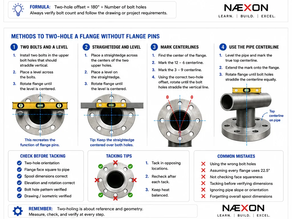
If you don’t have bolts available, you can use the flange face itself.
Select the two bolt holes that should straddle the top centerline.
Place a straightedge across their centers.
Then place your level on the straightedge.
Rotate the flange until the straightedge is level.
The challenge is keeping the straightedge accurately centered over both bolt holes.
If one end is slightly high or low because it is not positioned through the true hole centers, you can introduce an error.
For rough field work this may be adequate, but for precise fabrication, using bolts, pins or accurately marked centerlines is better.
Method 3: Use a Combination Square
A combination square can work well on smaller flanges.
First establish the vertical centerline of the pipe.
Then establish the corresponding centerline on the flange face.
Once you know the bolt-hole spacing angle, you can locate where the nearest bolt holes should fall relative to that line.
For example, on an 8-hole flange:
Bolt spacing = 45°
Half spacing:
22.5°
That means the two upper bolt holes should fall at:
22.5° left of vertical
and
22.5° right of vertical
Use the combination square and layout marks to verify that relationship before tacking.
Method 4: Mark the Flange Centerlines
This method takes longer but teaches the geometry better than almost any shortcut.
Find the center of the flange.
Then mark:
12–6 o’clock centerline
and
3–9 o’clock centerline
Now determine the bolt-hole spacing.
Formula:
Bolt-hole spacing angle = 360° ÷ Number of holes
Examples:
4 holes
360 ÷ 4 = 90°
8 holes
360 ÷ 8 = 45°
12 holes
360 ÷ 12 = 30°
16 holes
360 ÷ 16 = 22.5°
For a two-holed flange, rotate the pattern half of one bolt spacing.
Formula:
Two-hole rotation = 180° ÷ Number of holes
Examples:
Bolt Holes
Bolt Spacing
Two-Hole Rotation
4
90°
45°
8
45°
22.5°
12
30°
15°
16
22.5°
11.25°
This table makes it easy to understand why different flanges require different clocking.
Method 5: Measure Chord Distance Between Bolt Holes
You can also verify bolt-hole orientation using chord measurements.
A chord is the straight-line distance between two points on a circle.
If you know the bolt-circle diameter and the angular spacing, the chord between adjacent holes is:
Chord = 2R × sin(θ ÷ 2)
Where:
R = bolt-circle radius
θ = angle between the bolt holes
This method is more useful for layout and verification than for quickly two-holing a flange, but it can help when bolt-hole locations need to be reconstructed or checked.
For example, if the bolt-hole pattern is damaged, obscured or being laid out manually, chord dimensions allow you to accurately locate each hole around the bolt circle.
Method 6: Use the Pipe Centerline
If the pipe itself is already installed and level, it can become your reference.
Mark the true top centerline of the pipe using a level.
Extend that mark onto the flange.
Then rotate the flange until the bolt-hole pattern straddles that centerline equally.
This is often easier than trying to level directly from the flange when working on a long spool.
The important part is making sure the pipe is actually level first.
If the pipe is intentionally sloped, you must reference the required flange orientation rather than assuming gravity level is correct.
What If the Pipe Is Vertical?
Two-holing a flange on a vertical pipe requires a different reference.
You cannot simply put a level across the top bolts and assume that gives you the correct clocking relative to the system.
Instead, establish a known plant or drawing reference.
That might be:
- North
- South
- East
- West
- Equipment centerline
- Structural gridline
- Pipe rack reference
Then clock the flange relative to that direction.
A flange can be perfectly level and still be incorrectly rotated.
This is why orientation and level are not the same thing.
What If the Pipe Is Sloped?
This is another common trap.
Suppose a process line intentionally runs downhill.
If you simply place a level across your bolt holes and make the flange gravity-level, that may or may not match the required orientation.
You need to know what the drawing calls for.
The flange may need to remain:
Two-holed relative to true vertical
or
Two-holed relative to the pipe
depending on the project design.
Never assume.
Check the isometric, spool drawing or project standard.
Two-Hole Does Not Always Mean Correct
A flange can be perfectly two-holed and still be wrong.
You also need to verify:
Face squareness
Elevation
Rotation
Centerline
Flange face orientation
Bolt-hole orientation
Overall spool dimension
Required gap
Branch clocking
This is why good pipefitters don’t stop checking once the bubble is centered.
The flange is only one part of the geometry.
Check Flange Face Squareness
Before tacking, make sure the flange face is square to the pipe centerline unless the design calls for something different.
Use:
Square
Straightedge
Level
Tape
or approved shop tooling.
Check more than one location around the flange.
A flange can look square from one side and still be kicked on another.
This becomes especially important on larger diameter pipe.
Tack Placement Matters
Once the flange is properly positioned, tack placement matters.
If you put one large tack on one side and then weld another directly beside it, heat can begin pulling the flange out of alignment.
A better approach is to tack in opposing locations while repeatedly checking:
Two-hole
Square
Face
Dimension
Think of the flange like a wheel.
If you tack one side, check the opposite side.
Keep the heat balanced.
And recheck after each tack.
Never Trust the First Tack
This is a good fabrication habit:
Fit it. Check it. Tack it. Check it again.
The flange can move while being tacked.
A small tack can pull the face.
The pipe may spring.
The fitter may bump the flange.
The spool may shift on the stands.
So after the first tack, verify everything again.
Then after the second tack, verify again.
You want to catch movement while it is still easy to correct.
What About Slip-On Flanges?
Slip-on flanges introduce another consideration because the pipe slides inside the flange.
You must establish:
Pipe insertion depth
Flange face projection
Two-hole orientation
Face squareness
before final welding.
If the flange moves deeper onto the pipe while being adjusted, your overall spool dimension can change even though the bolt holes remain perfectly aligned.
That is why dimensions and orientation need to be checked together.
What About Weld-Neck Flanges?
A weld-neck flange typically gives you a more defined butt-weld fit-up at the hub.
You still need to check:
Root gap
Hi-lo
Face squareness
Two-hole orientation
Overall dimension
If you’re fitting a weld-neck flange onto a pipe spool, clocking the bolt holes is only one part of the fit.
What About Orifice Flanges?
Do not automatically treat an orifice flange like a normal flange.
Orifice flange assemblies can have additional orientation requirements because of taps and instrumentation.
The tap locations matter.
The drawing and project specification control.
Never rotate an orifice flange simply to make the bolt pattern look correct without confirming the required tap orientation.
Equipment Flanges Are Different
When connecting piping to pumps, compressors, exchangers or other equipment, the equipment flange establishes the final orientation.
You don’t force the equipment nozzle to match your spool.
The spool is fabricated and aligned to the equipment according to the approved drawings and tolerances.
Forcing mismatched piping into position can introduce nozzle loads and alignment problems.
Good bolt-up starts with good fabrication.
One rushed flange today can become tomorrow’s leak or alignment issue. Næxon discusses that same principle in The $100,000 Mistake: 35 Tiny Jobsite Habits That Can End a Career in Seconds. (Naexon)
A Fast 8-Hole Flange Example
Suppose you’re fitting an 8-hole flange.
You want it two-holed.
Step 1
Calculate bolt spacing:
360° ÷ 8 = 45°
Step 2
Calculate half spacing:
45° ÷ 2 = 22.5°
So the upper bolt holes sit:
22.5° left
and
22.5° right
of the 12 o’clock centerline.
Step 3
Install temporary bolts through those two holes.
Step 4
Place a level across the bolts.
Step 5
Rotate the flange until the bubble is centered.
Step 6
Verify:
Face square
Dimension correct
Flange orientation correct
Step 7
Tack.
Step 8
Recheck.
That is effectively two-holing a flange without dedicated flange pins.
A 12-Hole Example
For 12 bolt holes:
360 ÷ 12 = 30° per hole
Half:
30 ÷ 2 = 15°
The two upper holes should therefore lie approximately:
15° on either side of vertical
This is why simply memorizing 22.5° as “two-hole” is wrong.
22.5° only applies to specific bolt counts such as an 8-hole pattern.
The number of bolt holes controls the angular relationship.
A 16-Hole Example
For 16 holes:
360 ÷ 16 = 22.5°
Half:
22.5 ÷ 2 = 11.25°
So the correct two-hole offset is:
11.25°
That small angle makes visual guessing much less reliable.
On larger flanges, a small angular error can translate into a noticeable linear error at the bolt circle.
That is why using proper references matters.
Why Eyeballing Can Fool You
The human eye is surprisingly good at seeing gross misalignment.
It is not good at reliably distinguishing small angular errors on a circular bolt pattern.
A flange can look perfect and still be several degrees off.
The larger the bolt circle, the larger the linear displacement created by that angular error.
So while an experienced fitter may be able to get extremely close by eye, measurement is what turns close into correct.
Don’t Confuse Flange Hole Count With Pipe Size
Pipe size does not tell you the two-hole angle by itself.
You must know the actual flange bolt-hole count.
Different pressure classes and flange types can have different bolt patterns.
Always verify the flange you physically have or reference the applicable standard/drawing.
Do not assume:
“It’s a 6-inch flange, so it has X holes.”
The flange class matters.
Two-Holing With a Torpedo Level
A torpedo level works well when space is limited.
Insert two bolts or other approved temporary pins into the top holes.
Lay the torpedo level across them.
Center the bubble.
Because the level is short, however, small height differences can be harder to see than with a longer level.
For precision work, a longer reference generally magnifies small angular errors and can make them easier to detect.
Homemade Temporary Flange Pins
In some fabrication environments, workers make temporary alignment tools from suitable round stock or bolts.
If doing so, remember the purpose:
You want two straight, repeatable reference points sitting accurately in the bolt holes.
They should not be loose enough to lean significantly.
Dedicated flange pins are preferable because they are designed for the task.
Næxon also covers the broader tradition of craftsmen creating jobsite tooling in Built by the Trades: Why the Best Jobsite Gear Often Starts With a Worker Saying “I Can Make That Better”. (Naexon)
The same culture produced tools like the pipefitter push-pull, a temporary mechanical fit-up tool used to make controlled adjustments during pipe fabrication. (Naexon)
Common Mistakes
Most two-hole errors are simple:
- Leveling from the wrong bolt-hole pair
- Assuming every flange uses a 22.5° offset
- Not checking whether the pipe itself is level
- Forgetting intentional pipe slope
- Clocking a vertical flange without a directional reference
- Tacking before checking face squareness
- Allowing tack heat to pull the flange
- Failing to check the overall spool dimension
- Using loose bolts that lean inside oversized holes
- Assuming a mating flange will “pull it into place”
That final mistake is especially bad.
Bolts should not be used as a substitute for proper alignment.
The Geometry Shortcut
If you remember only one formula from this lesson, remember:
Two-hole angle = 180° ÷ Number of bolt holes
Examples:
4 holes → 45°
8 holes → 22.5°
12 holes → 15°
16 holes → 11.25°
That tells you how far the nearest bolt holes should sit from a primary centerline when the flange is properly two-holed.
Field Sequence
A reliable sequence is:
1. Verify the correct flange.
2. Verify the bolt-hole count.
3. Establish the pipe/flange centerline.
4. Determine the correct two-hole angle.
5. Select the correct upper bolt-hole pair.
6. Install temporary bolts if flange pins aren’t available.
7. Level across the bolt centers.
8. Check flange face squareness.
9. Check spool dimension.
10. Verify orientation against the drawing.
11. Tack opposing locations.
12. Recheck everything.
13. Complete fit-up according to the approved welding procedure.
Two-Holing Is Really About Reference
Flange pins are convenient.
They are not what makes the flange accurate.
The accuracy comes from understanding the reference geometry.
Once you understand:
centerline
bolt-circle spacing
half-hole rotation
level
orientation
you can reproduce the same relationship with several different tools.
That is the bigger lesson.
A skilled fitter should know how to use the specialized tool.
But he should also understand the geometry well enough to keep working when the specialized tool isn’t in his bucket.
And that is the difference between simply using flange pins and actually understanding how to two-hole a flange.


