A valve symbol may occupy less than an inch on a P&ID, but that little mark can tell you something important about how an entire process is intended to operate.
Is the valve there strictly for isolation? Is it intended to throttle flow? Does it operate with a quarter turn? Is it protecting an instrument connection? Why did the designer specify a globe valve instead of a gate valve?
Once you can answer questions like these, you’re doing more than recognizing symbols. You’re beginning to understand the process.
In Part 1: Valve Symbol Fundamentals, we established the basic method: follow the process line, identify the valve body, look for the operator, read the tag, and check the project legend whenever something is unclear.
Now we’ll apply that method to the manual valves you’ll encounter throughout industrial piping systems.
What Makes a Valve “Manual”?
A manually operated valve requires a person to physically change its position.
Depending on the valve, that might involve a:
Handwheel
Lever
Gear operator
T-handle
Chain wheel
The important distinction on a P&ID is that the valve isn’t being positioned automatically by a pneumatic, electric, or hydraulic actuator as part of a process-control function.
That doesn’t mean the valve is unimportant.
Manual valves perform some of the most fundamental functions in a plant: isolation, bypassing, draining, venting, throttling, equipment isolation, and maintenance access.
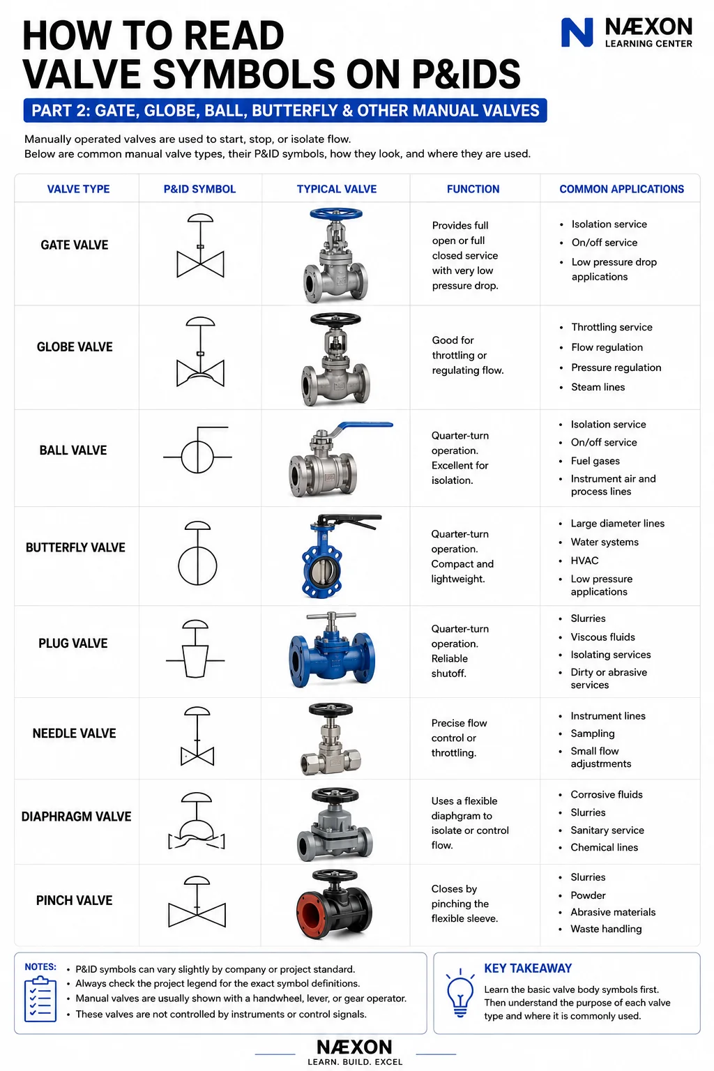
1. Gate Valve
The gate valve is one of the most recognizable valves in industrial piping.
Its primary strength is straightforward:
Isolation.
Inside the valve, a gate moves into or out of the flow path.
When fully open, the gate is withdrawn from the primary flow path, allowing relatively unrestricted flow through the valve.
When closed, the gate moves across the flow path to provide shutoff.
What Gate Valves Are Good At
Gate valves are commonly selected where the desired operating condition is:
Fully open
or
Fully closed
They are generally not the first choice for routine throttling.
Operating a gate valve partially open can expose internal components to unfavorable flow conditions, vibration, erosion, and wear depending on the service and valve design.
Think:
GATE = ISOLATION
When you recognize a gate valve on a P&ID, start by asking what equipment or section of piping that valve allows operators to isolate.
2. Globe Valve
A globe valve is built differently.
Instead of simply removing a gate from the flow path, a globe valve forces the process through a more restrictive internal path while a disc or plug moves relative to a seat.
That creates more pressure drop than a typical fully open gate valve.
But it also gives the globe valve an important advantage:
Better throttling and flow regulation.
Globe valves are commonly associated with applications where flow needs to be adjusted rather than simply turned completely on or off.
Depending on service and design, they may be found around:
Steam systems
Bypasses
Process lines
Utility systems
Flow-regulation applications
This doesn’t mean every throttling valve is a globe valve or every globe valve is used for throttling.
The P&ID, valve list and specifications determine the actual application.
Think:
GLOBE = REGULATION
3. Ball Valve
Ball valves use a rotating ball containing a bore through its center.
When the bore aligns with the pipe, the flow path is open.
Rotate the ball approximately 90 degrees and the solid portion of the ball blocks the flow path.
That makes the ball valve a:
Quarter-turn valve.
Ball valves can provide fast operation and excellent shutoff in many services.
They’re extremely common across industrial piping.
You may encounter them in:
Process piping
Utility piping
Fuel-gas systems
Instrument connections
Drains
Vents
Small-bore piping
Isolation applications
A lever-operated ball valve also gives workers a useful visual indication in many installations: lever orientation commonly corresponds to the ball position, although field verification and facility procedures always take priority.
Think:
BALL = QUICK QUARTER-TURN ISOLATION
4. Butterfly Valve
Butterfly valves are also quarter-turn valves.
Instead of a bored ball, however, they use a disc positioned inside the flow path.
Rotating the shaft turns the disc.
A butterfly valve is particularly attractive where engineers want a valve that can be relatively:
Compact
Lightweight
Simple
and practical for larger pipe diameters.
Butterfly valves are commonly encountered in services such as:
Cooling water
Utility water
HVAC systems
Fire-water systems
Large-diameter process or utility piping
The exact service depends heavily on valve design, seat material, pressure, temperature, process compatibility and project specifications.
Think:
BUTTERFLY = COMPACT QUARTER-TURN VALVE
5. Plug Valve
A plug valve uses a rotating plug inside the valve body.
Like ball and butterfly valves, many plug valves operate through approximately 90 degrees.
The internal plug contains a passage that aligns with the piping when open.
Rotate the plug and the passage moves out of alignment, restricting or stopping flow.
Plug valves may be encountered in:
Hydrocarbon service
Gas service
Slurries
Viscous services
Dirty process applications
Isolation service
Different plug-valve designs can behave very differently, so don’t assume every plug valve is interchangeable.
Think:
PLUG = ROTATING QUARTER-TURN SHUTOFF
6. Needle Valve
Needle valves are common around instrumentation and small-bore piping.
Instead of moving a large gate or disc, the valve uses a slender, tapered stem or needle that moves precisely relative to a seat.
This allows very fine adjustment.
That’s why needle valves are often associated with:
Instrument lines
Pressure gauges
Sampling systems
Small-bore tubing
Controlled bleed applications
Low-flow adjustment
If you’re tracing instrument piping on a P&ID, needle valves become especially important.
Think:
NEEDLE = FINE CONTROL
7. Diaphragm Valve
A diaphragm valve uses a flexible diaphragm as part of its closure mechanism.
Instead of relying on the process fluid contacting a conventional stem and packing arrangement in the same way as many other valves, the diaphragm can provide separation between operating components and the process.
Depending on the design, diaphragm valves can be useful in:
Chemical service
Corrosive service
Slurries
Water treatment
Sanitary processes
High-purity applications
Material compatibility is extremely important because the diaphragm itself must withstand the process conditions.
Think:
DIAPHRAGM = FLEXIBLE BARRIER
8. Pinch Valve
The name practically explains how this valve works.
A pinch valve contains a flexible sleeve or tube.
The valve closes by compressing—or pinching—that flexible flow path.
Because of this construction, pinch valves can be useful for certain difficult materials, including:
Slurries
Powders
Abrasive materials
Waste streams
Suspended solids
They’re far less common than gate, globe, ball or butterfly valves in many refinery piping systems, but recognizing the concept is still useful when reading drawings across different industries.
Think:
PINCH = FLEXIBLE SLEEVE
Don’t Identify a Valve From the Handwheel Alone
This is an easy beginner mistake.
You see a handwheel and immediately think:
Gate valve.
Not necessarily.
Gate valves can have handwheels.
Globe valves can have handwheels.
Needle valves can have handwheels.
Gear-operated butterfly valves may have handwheels.
The operator tells you how the valve is operated.
The valve-body designation tells you what type of valve it is.
Keep those two pieces of information separate when reading the drawing.
Quarter-Turn vs. Multi-Turn Valves
Another useful way to organize manual valves is by how they operate.
Common Quarter-Turn Designs
Ball valve
Butterfly valve
Plug valve
These typically move from open to closed through approximately a 90-degree rotation of the closure element.
Common Multi-Turn Designs
Gate valve
Globe valve
Needle valve
These typically require multiple rotations of a handwheel or stem mechanism to move between positions.
Understanding this difference can help connect the schematic symbol to the physical valve you eventually encounter in the field.
Isolation vs. Throttling
Here’s another distinction every P&ID reader should understand.
Isolation
The primary objective is stopping flow so a section of the process can be separated.
Common examples may include:
Gate valves
Ball valves
Plug valves
Butterfly valves
depending on service.
Throttling
The valve intentionally operates somewhere between fully open and fully closed to influence flow or pressure.
Common examples may include:
Globe valves
Needle valves
and purpose-designed control valves.
But don’t turn this into a rigid memorization rule.
Valve selection depends on many factors:
Pressure
Temperature
Fluid
Required shutoff
Flow characteristics
Pressure drop
Corrosion
Erosion
Valve size
Maintenance requirements
Project specifications
The symbol tells you what was selected.
Engineering documentation tells you why.
Follow the Valves Around Equipment
One of the fastest ways to understand manual valves on a P&ID is to study how they’re arranged around equipment.
Imagine:
VESSEL → GATE VALVE → PUMP → CHECK VALVE → GATE VALVE → PROCESS
The valves surrounding the pump may provide isolation so maintenance can be performed on that equipment.
Now imagine a smaller line around a control valve:
Isolation Valve → Control Valve → Isolation Valve
with a bypass around the assembly.
That arrangement tells you considerably more than simply recognizing three valve symbols.
You’re beginning to recognize valve arrangements.
And valve arrangements are where P&ID reading becomes genuinely useful.
Look for Drains and Vents
Small valves branching from major process lines shouldn’t automatically be ignored.
A small valve on the bottom of a line may be associated with a drain.
A small valve at a high point may be associated with a vent.
Those connections can become important during:
Hydrotesting
Draining
Depressurizing
Maintenance
Commissioning
Shutdowns
Line breaking
If you’re unfamiliar with terminology commonly used during these activities, the Næxon Refinery Turnaround Dictionary: 100 Terms Every Shutdown Worker Should Know covers isolation, blinds, line breaks, vents, work packages, tie-ins, hydrotesting and other shutdown terminology.
What the P&ID May Not Tell You
Suppose the drawing identifies a gate valve.
That doesn’t necessarily tell you everything required to purchase, fabricate, install or maintain it.
Additional project documents may define:
Valve size
Pressure class
Body material
Trim
End connections
Bonnet design
Seat material
Packing
Specification
Valve number
Manufacturer requirements
That information may come from the valve list, piping material specification, line list, equipment documentation or other project records.
This is why experienced workers don’t try to force one drawing to answer every question.
Always Check the Project Legend
Valve symbols aren’t perfectly universal.
ISA standards, company standards, engineering-contractor practices and legacy plant drawings can all influence how symbols are represented.
Even drawings within the same facility can differ if they were created decades apart.
So if you encounter a symbol that looks unfamiliar:
Don’t guess.
Find the legend.
Check the valve list.
Check the applicable project standard.
Confirm what the symbol means on that drawing.
That habit is more valuable than memorizing a hundred symbols without context.
Quick Field Recognition
When you’re trying to build speed, associate each valve with its basic operating concept:
Gate Valve — Isolation
Globe Valve — Throttling
Ball Valve — Quarter-turn isolation
Butterfly Valve — Compact quarter-turn operation
Plug Valve — Rotating plug shutoff
Needle Valve — Fine adjustment
Diaphragm Valve — Flexible diaphragm
Pinch Valve — Flexible sleeve
These are learning shortcuts—not engineering specifications.
Actual service and suitability must always be determined from the project’s documentation.
Test Yourself
You’re following a P&ID and find a manual valve upstream of a pump.
What should you ask?
What type of valve is it?
Is it intended for isolation?
What is its normal position?
Is another isolation valve located downstream?
Is there a check valve on the discharge?
Are drains or vents provided?
What equipment does the line connect to next?
Notice what happened.
You stopped asking:
“What does this symbol mean?”
and started asking:
“What is this system doing?”
That’s exactly where you want to be.
From Individual Valves to Complete Systems
Learning valve symbols is similar to learning words before learning sentences.
A gate-valve symbol by itself tells you something.
A gate valve upstream of a pump tells you more.
A gate valve, pump, check valve, flow transmitter and control valve arranged in sequence begin telling you how an entire process functions.
That’s why the goal of this series isn’t simply memorization.
The goal is to reach the point where you can open an unfamiliar P&ID, find a process line and begin following what happens to the process from one piece of equipment to the next.
For workers building broader refinery knowledge, the Næxon Refinery Turnaround Dictionary is a useful companion reference while learning the terminology found around industrial piping systems.
Coming Next
How to Read Valve Symbols on P&IDs — Part 3: Check Valves & Flow Direction
Manual valves tell us where operators can isolate or regulate a process.
Check valves introduce another critical piece of information:
direction.
In Part 3, we’ll break down standard check valves, swing checks, lift checks, ball checks, dual-plate checks and other common designs. More importantly, we’ll learn how to determine which direction the process is supposed to flow and how to recognize when a check valve’s orientation matters.
By the end of Part 3, you’ll be able to look at a check-valve symbol and understand not just what it is—but what it’s preventing from happening.


