Some valves control the process.
Others are there for the moment when the process stops behaving the way it should.
Pressure rises beyond its intended limit. A vessel begins pulling vacuum. Equipment needs to depressurize during an emergency. A downstream system requires controlled pressure regardless of what is happening upstream.
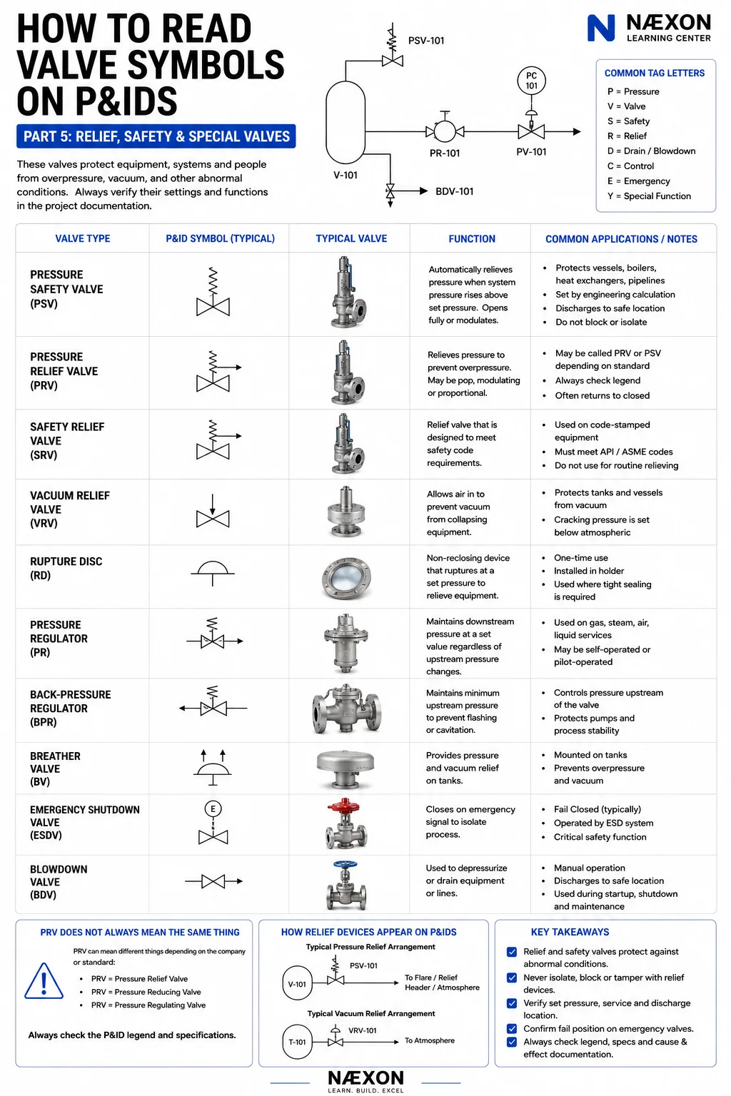
Those situations introduce an entirely different group of symbols on a P&ID: relief, safety, pressure-regulating, shutdown, blowdown and other special-purpose valves and devices.
These aren’t symbols you want to misunderstand.
In the previous parts of this series, we’ve worked from basic valve symbols into manual valves, check valves, flow direction, actuators and control valves. Part 5 adds the devices designed to protect equipment, manage abnormal pressure conditions and place processes into safer states.
Start With the Reason the Valve Exists
When you encounter one of these devices on a P&ID, don’t begin by memorizing its abbreviation.
Ask:
What condition is this device protecting against?
Is it protecting a vessel against excessive pressure?
Preventing a tank from collapsing under vacuum?
Maintaining downstream pressure?
Maintaining upstream pressure?
Isolating the process during an emergency?
Rapidly depressurizing equipment?
Once you know the purpose, the symbol becomes much easier to understand.
1. Pressure Safety Valve — PSV
One of the most important devices you’ll encounter is the:
PSV — Pressure Safety Valve
A PSV protects pressure-containing equipment against overpressure.
Imagine a vessel designed to operate at a certain pressure.
Under abnormal conditions, pressure begins increasing.
Without adequate protection, that pressure could eventually exceed the safe limits of the equipment.
The PSV provides a designed relief path.
At its specified set pressure, the valve responds according to its design and service, allowing process fluid to discharge into an appropriate relief system or destination.
That destination might include a:
Flare header
Relief header
Vent system
Recovery system
or another engineered discharge location.
Think:
PSV = OVERPRESSURE PROTECTION
A PSV Is Not a Normal Process-Control Valve
This distinction matters.
A normal control valve may continuously move to maintain a process variable.
A PSV exists primarily as a protective device.
During normal operation, you generally expect it to remain closed.
It becomes active when the protected system reaches the conditions for which the device was designed to respond.
That means when you find a PSV on a P&ID, immediately look at:
What equipment is it protecting?
and:
Where does it discharge?
Those two questions tell you a tremendous amount about the system.
Reading a PSV Arrangement
Imagine:
V-101 → PSV-101 → FLARE HEADER
V-101 is the protected vessel.
PSV-101 is the pressure safety valve.
The discharge line leads to the flare or relief system.
Now the drawing isn’t simply telling you:
“There is a safety valve here.”
It’s telling you:
If the protected system reaches the relief condition, this is the engineered discharge path.
That’s a much more useful way to read the P&ID.
2. Pressure Relief Valve
You’ll also encounter the term:
Pressure Relief Valve
Like a safety valve, a pressure relief valve protects equipment against excessive pressure.
Historically and technically, terminology can differ depending on fluid service, applicable code, valve behavior and company standards.
You’ll encounter terms including:
Safety valve
Relief valve
Safety relief valve
and combinations of them.
For someone reading a P&ID, the important lesson is:
Don’t casually treat every relief-device abbreviation as interchangeable.
Check the project legend, equipment documentation, relief-device data and applicable specifications.
3. Safety Relief Valve — SRV
A safety relief valve combines characteristics associated with safety and relief valve service depending on the design and applicable standard.
You may encounter the abbreviation:
SRV
The exact terminology and intended service should be confirmed from the project’s documentation.
From the P&ID-reader’s perspective, the major concept remains:
This is a pressure-protection device.
Find what it protects.
Find where it relieves.
Then consult the relevant project documentation for its specific design basis.
The PRV Problem
Now we reach one of the most confusing abbreviations in industrial piping:
PRV
Ask three different people what PRV means and you may hear:
Pressure Relief Valve
Pressure Reducing Valve
Pressure Regulating Valve
That is precisely why blindly memorizing abbreviations can get you into trouble.
The surrounding process usually provides clues.
But the final authority is the:
P&ID legend
Valve list
Instrument index
Project specification
or applicable documentation.
Never interpret PRV from the letters alone when the project hasn’t defined it.
Pressure Relief vs. Pressure Reducing
These two concepts are completely different.
A pressure relief device protects against excessive pressure by providing a relief path when pressure reaches a specified condition.
A pressure-reducing regulator intentionally lowers pressure from a higher upstream pressure to a controlled lower downstream pressure during normal operation.
For example:
150 psi supply
↓
Pressure-reducing regulator
↓
50 psi downstream system
That regulator is actively maintaining a lower downstream pressure.
It isn’t waiting for an emergency overpressure event in the same way a PSV is.
4. Pressure Regulator
A pressure regulator can automatically control pressure using process pressure itself, a pilot system, or another arrangement depending on the design.
One common application is maintaining:
Downstream pressure.
Imagine:
High-pressure header → regulator → lower-pressure system
If upstream pressure changes, the regulator adjusts to help maintain the desired downstream condition.
Regulators are common in systems involving:
Natural gas
Fuel gas
Steam
Instrument air
Nitrogen
Water
and many other services.
Think:
PRESSURE REGULATOR = MAINTAIN CONTROLLED PRESSURE
5. Back-Pressure Regulator
A back-pressure regulator generally works from the opposite perspective.
Rather than primarily maintaining downstream pressure, it is commonly used to maintain a required pressure upstream of the regulator.
Consider a process that requires a minimum pressure before fluid is allowed to leave.
The back-pressure regulator can restrict the outlet to help maintain that upstream pressure.
Think:
PRESSURE-REDUCING REGULATOR → controls downstream pressure
BACK-PRESSURE REGULATOR → controls upstream pressure
That’s a useful learning shortcut.
Actual function should still be confirmed from the P&ID and project documentation.
6. Vacuum Relief Valve
Pressure doesn’t have to become too high to damage equipment.
It can also become too low.
Imagine a storage tank being emptied rapidly.
Liquid leaves the tank, but insufficient vapor or air enters to replace the lost volume.
Internal pressure falls below atmospheric pressure.
If the tank isn’t designed for that vacuum condition, the external atmospheric pressure can become structurally significant.
A:
Vacuum Relief Valve — VRV
can provide protection by admitting air or another appropriate medium when the internal pressure falls below the device’s set condition.
Think:
VRV = VACUUM PROTECTION
Pressure Can Push Out. Vacuum Can Push In.
This is an important concept.
Workers naturally understand that excessive internal pressure can rupture equipment.
Vacuum failure is less intuitive.
When pressure inside a tank becomes sufficiently lower than the surrounding atmosphere, atmospheric pressure pushes inward on the equipment.
Large thin-walled tanks can be particularly vulnerable.
So when you see vacuum protection on a P&ID, ask:
What operating condition could pull this equipment into vacuum?
Draining?
Cooling?
Condensing steam?
Pump-out?
Blocked venting?
That question helps explain why the device exists.
7. Pressure/Vacuum Breather Valve
Storage tanks frequently need protection in both directions.
Pressure can increase as:
Liquid enters
Temperature rises
Vapor expands
and pressure can decrease as:
Liquid leaves
Temperature falls
Vapor condenses
A pressure/vacuum breather valve can help manage both conditions within its design limits.
You may also hear terminology such as:
Conservation vent
Pressure-vacuum vent
or other project-specific terms.
These devices are especially common on atmospheric and low-pressure storage systems.
8. Rupture Disc
A rupture disc is not a conventional reclosing valve.
It is a pressure-relief device containing a membrane designed to rupture at a specified condition.
Once it ruptures:
It does not simply reset itself.
The disc must be replaced.
Rupture discs may be installed:
By themselves
Upstream of a relief valve
Downstream of a relief valve
or in other engineered arrangements.
They can provide advantages involving tight sealing, corrosion isolation, rapid opening and specialized process requirements.
Think:
RUPTURE DISC = ONE-TIME PRESSURE-RELIEF ELEMENT
Rupture Disc + PSV
You may encounter a P&ID showing a rupture disc in combination with a PSV.
Why use both?
Depending on the design, the rupture disc may help isolate the PSV from:
Corrosive process material
Polymerizing material
Fouling
or provide another engineered benefit.
But combinations of rupture discs and relief valves require careful engineering because pressure can become trapped between devices and the arrangement can affect relief performance.
Never modify these systems casually.
9. Emergency Shutdown Valve — ESDV
Now we move from pressure relief to emergency isolation.
An:
ESDV — Emergency Shutdown Valve
is intended to move to a defined position when the emergency shutdown system demands it.
In many applications, that means:
Close quickly and isolate the process.
Examples might include:
Fuel supply
Hydrocarbon transfer
Process-unit boundaries
Tank connections
Pipeline interfaces
Critical equipment
An ESDV may be operated pneumatically, hydraulically or electrically depending on the system.
The important thing is that it forms part of a larger shutdown philosophy.
ESDV Does Not Simply Mean “Automatic Valve”
An ESDV isn’t just a convenient remotely operated isolation valve.
Its purpose is tied to an emergency or protective function.
That means you should look beyond the valve itself.
Ask:
What initiates the shutdown?
A high pressure?
High temperature?
Gas detection?
Fire detection?
Manual emergency pushbutton?
Compressor trip?
Loss of power?
Something else?
Those relationships may be shown through the P&ID, logic diagrams, cause-and-effect documentation or other control-system drawings.
Fail Position Matters on ESD Valves
An emergency shutdown valve often has a defined failure position.
For an isolation function, that may commonly be:
FC — Fail Closed
But don’t turn that into a universal rule.
Some emergency functions require a valve to open.
Others require it to remain in a defined state.
The correct action is determined by the process-safety design.
As we covered in Part 4: Control Valves & Actuators, normal position and failure position are different concepts.
10. Blowdown Valve — BDV
A:
BDV — Blowdown Valve
is commonly associated with depressurizing or removing inventory from equipment or piping.
During an emergency shutdown, isolating the process may not be enough.
Pressure can remain trapped inside:
Vessels
Compressors
Piping systems
Process equipment
A blowdown system can provide an engineered path for reducing that pressure.
Depending on the facility, discharge may be routed to a:
Flare system
Blowdown header
Recovery system
or another designated destination.
Think:
ESDV = ISOLATE
BDV = DEPRESSURIZE
That’s a useful conceptual distinction.
ESDV and BDV Working Together
Imagine a simplified process:
Feed → ESDV → V-101 → Process
V-101 also connects through:
BDV-101 → Flare Header
During a defined emergency condition, the shutdown system may command the ESDV closed to stop incoming material.
Then, according to the facility’s shutdown logic, the blowdown system may provide a controlled depressurization path.
Now you can see why reading individual symbols isn’t enough.
The valves work together as a protective system.
Relief Valve vs. Blowdown Valve
These are also easy to confuse.
A relief valve automatically protects equipment from overpressure at its set conditions.
A blowdown valve may be commanded open as part of an operating, shutdown or emergency depressurization sequence.
Both can ultimately discharge toward a flare or other safe disposal system.
But they perform different functions.
Follow the Relief Line
When you find a PSV on a P&ID, don’t stop at the valve.
Follow its discharge piping.
It might lead to:
Flare header
Relief header
Atmosphere where specifically permitted
Scrubber
Knockout drum
Recovery system
or another destination.
Then ask:
Where does this relieved material ultimately go?
That can reveal another major section of the plant’s protection system.
Relief Headers and Flare Systems
In many process facilities, multiple relief devices discharge into a common relief or flare network.
A simplified path might be:
Process Vessel
↓
PSV
↓
Relief Header
↓
Flare Knockout Drum
↓
Flare
The knockout drum helps separate entrained liquids before the vapor proceeds toward the flare system.
The actual system can be substantially more complicated.
But following that line on the P&ID teaches you where abnormal process inventory is intended to go.
Never Treat a Relief Device Like an Ordinary Isolation Valve
A relief device exists to protect equipment.
Blocking its required relief path can defeat that protection.
That is why valves around relief devices are subject to strict engineering and operating requirements.
Facilities may use:
Locked-open valves
Car-sealed-open valves
Administrative controls
Interlocked arrangements
or other engineered practices where isolation valves are permitted.
The exact arrangement is facility-specific.
Never assume a valve around a PSV can simply be closed because it has a handwheel.
Relief Set Pressure Is Not Operating Pressure
Another important distinction:
Normal operating pressure
is not necessarily:
Relief set pressure.
The process normally operates below the conditions at which the relief device is intended to activate.
The relationship between:
Operating pressure
Design pressure
Maximum allowable working pressure
Set pressure
Accumulation
and other pressure concepts is governed by applicable engineering requirements and codes.
A P&ID alone generally won’t teach you the entire relief calculation.
It shows how the protective device connects to the process.
Special Valves Around Tanks
Storage-tank P&IDs can contain a different collection of protective devices than high-pressure process vessels.
You might encounter:
Pressure/vacuum vents
Emergency vents
Breather valves
Flame arresters
Blanketing regulators
Vacuum breakers
Overflow arrangements
These devices work together to manage normal breathing, abnormal pressure, vacuum and vapor-control requirements.
Again, don’t interpret one symbol without looking at the entire tank system.
Nitrogen Blanketing
Some tanks maintain a nitrogen atmosphere above the stored liquid.
A simplified arrangement might include:
Nitrogen Header
↓
Pressure Regulator
↓
Tank Vapor Space
The regulator supplies nitrogen as needed to maintain the desired tank pressure.
Another device may provide pressure or vacuum protection.
This is a good example of several special valves working together:
Regulator = normal pressure management
Breather / vent = normal or abnormal breathing
Emergency protection = additional protective capacity
Each has a different job.
How to Read Any Relief or Special Valve on a P&ID
When you encounter one, use this sequence:
1. Identify the protected equipment.
Vessel? Tank? Compressor? Pipeline?
2. Identify the device.
PSV? VRV? Regulator? ESDV? BDV?
3. Determine its purpose.
Overpressure protection? Vacuum protection? Pressure regulation? Isolation? Depressurization?
4. Determine normal position.
Open? Closed? Modulating?
5. Determine failure position when applicable.
FO? FC? FL?
6. Follow the discharge or downstream line.
Where does the material go?
7. Look for associated instrumentation.
Pressure transmitter? Shutdown signal? Pilot?
8. Look for isolation valves.
How are they controlled or administratively managed?
9. Check the legend.
Especially when abbreviations such as PRV are involved.
10. Consult the applicable specifications and protective-system documentation.
The P&ID shows the relationship. It doesn’t replace the engineering basis.
Example — Pressure Vessel
Consider:
Feed → V-101 → Product
The vessel also has:
V-101 → PSV-101 → Relief Header
and:
V-101 → PT-101 → PIC-101 → PV-101
Now we can separate two functions.
PV-101 participates in normal pressure control.
PSV-101 provides overpressure protection.
That’s a crucial distinction.
The control valve tries to keep the process operating normally.
The PSV exists for conditions where pressure reaches its protective setpoint.
Example — Emergency Shutdown
Now add:
Feed → ESDV-101 → V-101
and:
V-101 → BDV-101 → Flare
You can now identify three layers:
Normal control
PV-101 controls pressure.
Emergency isolation
ESDV-101 can isolate feed.
Emergency depressurization / blowdown
BDV-101 provides the designed depressurization path when commanded.
And behind those layers:
Overpressure protection
PSV-101 remains available for its defined protective function.
One vessel.
Four different valve functions.
That’s why understanding the symbol’s purpose matters so much.
Safety and Maintenance
Relief and shutdown devices are critical safety equipment.
They should never be casually:
Blocked
Isolated
Adjusted
Gagged
Tampered with
Removed from service
or modified outside approved procedures.
Maintenance, testing and isolation must follow facility requirements and applicable engineering practices.
During shutdowns and turnarounds, understanding terminology such as positive isolation, line breaking, LOTO, zero-energy state, redlines and return to service becomes especially important. The Næxon Refinery Turnaround Dictionary: 100 Terms Every Shutdown Worker Should Know provides a useful companion reference for those concepts.
The Big Lesson From Part 5
When you see a special valve, stop asking only:
“What is this symbol?”
Ask:
“What abnormal condition is this device designed to control or protect against?”
A PSV tells you something about overpressure.
A vacuum relief valve tells you something about low-pressure risk.
A regulator tells you something about required pressure control.
An ESDV tells you something about emergency isolation.
A BDV tells you something about depressurization.
Once you start thinking that way, a P&ID begins revealing the plant’s protection philosophy, not just its piping.
Series Progress
Part 1 — Valve Symbol Fundamentals
Understanding how valve symbols are constructed.
Part 2 — Gate, Globe, Ball, Butterfly & Other Manual Valves
Recognizing common manual valve types.
Part 3 — Check Valves & Flow Direction
Understanding one-way flow and reverse-flow protection.
Part 4 — Control Valves & Actuators
Understanding automatic valves and control systems.
Part 5 — Relief, Safety & Special Valves
Understanding overpressure, vacuum, regulation, emergency isolation and depressurization.
Now we’re ready to connect the valves to the instrumentation around them.
Coming Next
How to Read Valve Symbols on P&IDs — Part 6: Valve Tags, Instrument Bubbles & Control Loops
In Part 6, we’ll take combinations such as:
FT-101 → FIC-101 → FV-101
PT-201 → PIC-201 → PV-201
LT-301 → LIC-301 → LV-301
and break them down piece by piece.
We’ll cover instrument identification letters, instrument bubbles, loop numbers, signal lines, transmitters, indicators, controllers, switches and final control elements.
This is where you stop reading a P&ID as a collection of equipment and start reading it as a working process-control system.


