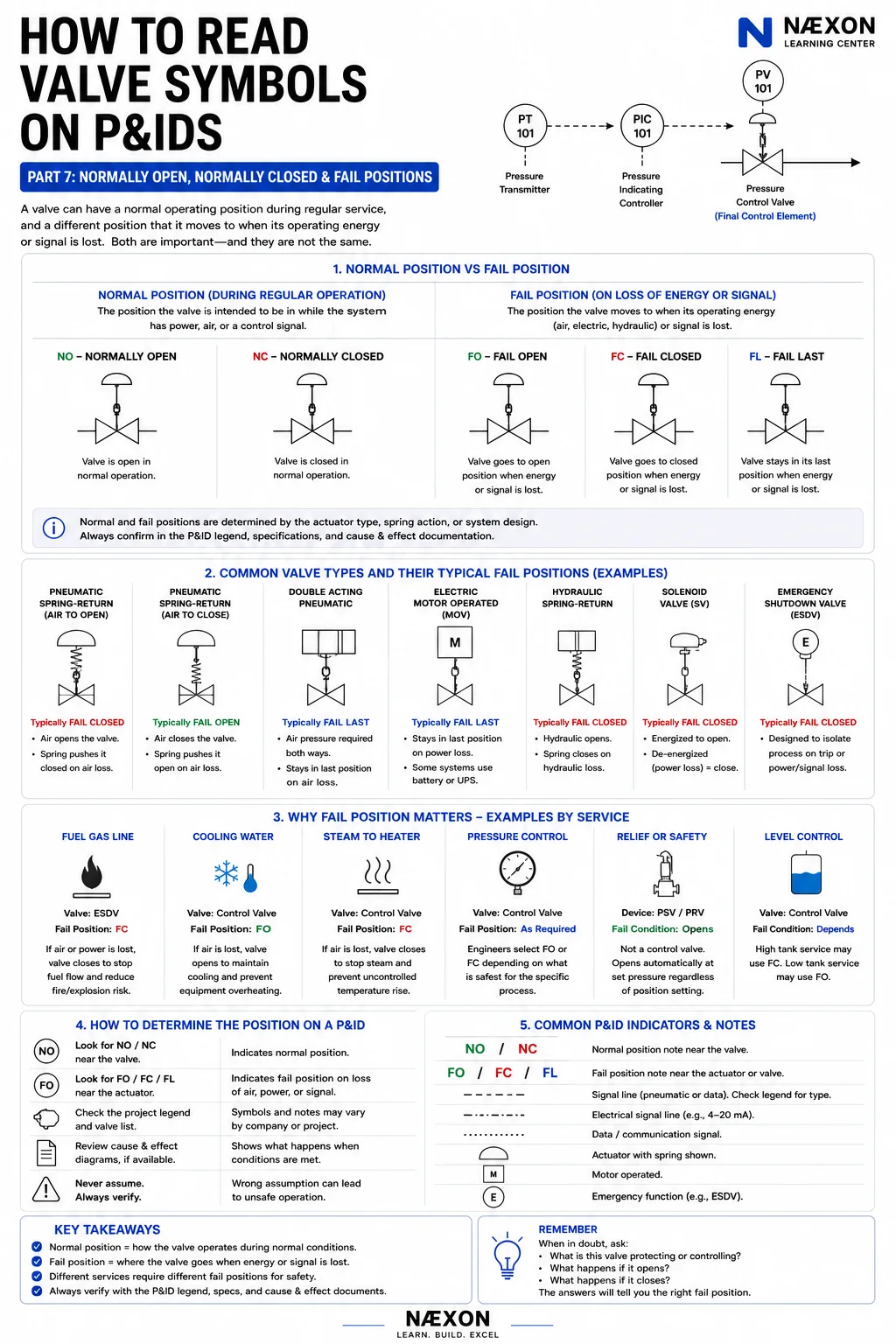
A valve can be open during normal operation and still be designed to close when its operating energy disappears.
Another valve can normally sit closed but automatically open during a failure.
That difference is one of the most important things to understand when reading actuated valves on a P&ID.
Because normal position and fail position are not the same thing.
In the earlier parts of this series, we covered valve fundamentals, manual valves, check valves, actuators, relief devices, instrument bubbles and control loops. Now we’re focusing on what happens when the system is operating normally—and what happens when something goes wrong.
Normal Position vs. Fail Position
Start with the basic distinction.
Normal Position
Normal position describes how the valve is intended to be positioned during the defined normal operating condition.
Common designations include:
NO — Normally Open
NC — Normally Closed
Fail Position
Fail position describes the position the valve is intended to move toward—or remain in—when a specified source of operating energy or signal is lost.
Common designations include:
FO — Fail Open
FC — Fail Closed
FL — Fail Last / Fail Locked / Fail in Place, depending on the project terminology.
The key point is:
A valve can have one normal position and a completely different failure position.
Normally Open — NO
A valve marked:
NO
is intended to be open under the normal operating condition defined by the project.
That doesn’t necessarily mean it is always fully open.
A modulating control valve may spend much of its operating life somewhere between fully open and fully closed.
So when projects use “normally open,” always understand what that designation means within their own operating philosophy.
For simple on/off valves, the concept is straightforward:
Normal operation = valve open
Normally Closed — NC
A valve marked:
NC
is intended to be closed during the defined normal condition.
Common examples may include:
Bypass valves
Drain valves
Vent valves
Blowdown valves
Emergency connections
depending on the system.
A normally closed valve may remain closed for months and only open during maintenance, startup, shutdown or an abnormal event.
But again:
NC tells you the normal condition—not necessarily the failure condition.
Fail Open — FO
A valve marked:
FO
is intended to move toward its open position following the specified loss of operating energy or control signal.
Why would engineers deliberately want a valve to open when something fails?
Because in some services, continued flow is safer than stopping flow.
A simplified example is cooling water.
Imagine a process requires cooling to prevent equipment from overheating.
If instrument air fails, engineers may decide that keeping cooling-water flow available is the safer response.
That valve might therefore be designed:
Fail Open
But this is only a general example.
The actual fail position must always be confirmed from the project documentation.
Fail Closed — FC
A valve marked:
FC
moves toward the closed position under the defined failure condition.
This is common where shutting off the process is the safer response.
A simplified example could involve:
Fuel gas
If the actuator loses instrument air or another control source, closing the valve may stop fuel flow.
That can help reduce escalation during certain abnormal conditions.
So the valve might be designed:
Fail Closed
Again, never assume all fuel-gas valves fail closed without checking the actual system.
Fail Last — FL
Some valves are intended to remain near their current position when operating energy or signal is lost.
You may see:
FL — Fail Last
or similar terminology such as:
Fail in Place
Fail Locked
A double-acting pneumatic actuator, for example, may require air pressure to move in either direction.
If both air supplies are lost and no spring drives the valve, the valve may tend to remain where it was, depending on the system and any lock-up devices.
That doesn’t automatically mean every double-acting actuator is truly fail-last.
Additional components can change the failure behavior.
Actuator Design Determines Fail Action
The fail position isn’t chosen by writing “FO” or “FC” beside the valve.
The physical actuator and system must actually be designed to make that happen.
A spring-return pneumatic actuator is a good example.
The actuator contains:
Air pressure
working against:
Spring force
If the air supply disappears, the spring pushes the actuator toward its mechanical failure position.
Depending on how the actuator is configured:
Loss of air can open the valve
or:
Loss of air can close the valve.
That is why terms such as:
Air-to-open
and:
Air-to-close
matter.
Air-to-Open
Suppose instrument air is required to open the valve.
The actuator is:
Air-to-open
If instrument air is lost, the spring moves the valve in the opposite direction.
That commonly produces:
Fail Closed
Simplified:
Air supplied → valve opens
Air lost → spring closes valve
Air-to-Close
Now reverse the arrangement.
Air pressure is required to close the valve.
The actuator is:
Air-to-close
If the air supply disappears, the spring drives the valve open.
That commonly produces:
Fail Open
Simplified:
Air supplied → valve closes
Air lost → spring opens valve
Why Spring Direction Matters
If you look closely at detailed actuator drawings or specifications, the spring arrangement helps determine failure action.
But on a P&ID, you generally shouldn’t try to reverse-engineer the actuator from appearance alone.
Look for:
FO
FC
FL
or other project-defined failure notation.
Then confirm with:
Valve data sheets
Instrument index
Cause-and-effect diagrams
Control narratives
Vendor documentation
when necessary.
Double-Acting Pneumatic Actuators
A double-acting actuator uses pneumatic pressure to move the valve in both directions.
For example:
Air to one side → opens
Air to opposite side → closes
Without a spring, a complete loss of air doesn’t inherently force the valve fully open or closed.
Depending on the design, the valve may:
Remain near its last position
Move due to process forces
Move using stored energy
Move through an accumulator system
or respond through another engineered arrangement.
So never see “double acting” and automatically assume:
Fail Last
The complete system determines the result.
Motor-Operated Valves and Failure Position
Motor-operated valves introduce another important distinction.
An MOV uses electrical energy to move the valve.
If electrical power suddenly disappears, many MOVs simply stop moving and remain near their current position.
But some systems include:
Battery backup
UPS power
Stored-energy devices
Spring-return mechanisms
or emergency electrical supplies.
That means a motor-operated valve’s failure behavior depends on the actual design.
Don’t assume:
MOV = fail last
even though that may occur in many ordinary arrangements.
Hydraulic Actuators
Hydraulic actuators can be configured in several ways.
Some use hydraulic pressure in both directions.
Others use:
Hydraulic pressure + spring return
An accumulator may also provide stored hydraulic energy during a failure.
This is common in applications where large forces and reliable emergency movement are required.
Again, the P&ID may tell you the intended failure position.
The hydraulic schematic or vendor documentation explains exactly how it happens.
Solenoid Valves and Fail Action
Solenoid valves often play a critical role in emergency and shutdown valve systems.
Imagine a spring-return ESDV.
During normal operation, the solenoid keeps instrument air supplied to the actuator.
Then an emergency shutdown signal occurs.
The solenoid de-energizes.
Instrument air is vented.
The spring drives the process valve closed.
Simplified:
Normal electrical signal
↓
Solenoid energized
↓
Air supplied
↓
ESDV held open
Then:
Shutdown signal / power loss
↓
Solenoid de-energizes
↓
Air vents
↓
Spring closes ESDV
This is one common de-energize-to-trip philosophy.
Actual systems vary, so always verify the design.
Emergency Shutdown Valves
In Part 5, we introduced:
ESDV — Emergency Shutdown Valve
Many ESDVs are designed to isolate hazardous process inventory.
Because of that, a common failure philosophy is:
Fail Closed
But some emergency valves exist specifically to open.
Examples can include:
Depressurization valves
Cooling valves
Quench valves
or other protective functions.
So never equate:
Emergency = closed
The safe direction depends entirely on what the valve is supposed to accomplish.
Blowdown Valves
A blowdown valve may normally be:
Closed
during regular process operation.
During a defined emergency, it may be commanded:
Open
to depressurize equipment.
This creates an important example:
Normal position = Closed
but its commanded emergency action may be:
Open
Depending on actuator design, the fail position could also be open, closed, or handled through a separate safety logic philosophy.
This is why three questions may need separate answers:
What is its normal position?
What happens when the ESD system trips?
What happens when actuator energy itself is lost?
Those are not automatically identical.
Cooling Water Example
Imagine a control valve supplying cooling water to a critical exchanger.
The process generates substantial heat.
If control air disappears and the cooling valve closes, the process could overheat.
Engineers may therefore choose:
Fail Open
for that valve.
Conceptually:
Loss of control energy → maximum cooling available
This is a classic example used to teach fail-safe philosophy.
But the actual design still depends on the consequences of excessive cooling, downstream limitations and the process itself.
Fuel Gas Example
Now imagine a valve feeding fuel to a fired heater.
If control energy is lost, continuing unrestricted fuel flow could create a dangerous condition.
A common design philosophy may therefore be:
Fail Closed
Conceptually:
Loss of control energy → stop fuel flow
Again, this is not a substitute for the actual P&ID and burner-management documentation.
Steam to a Heater
Consider steam feeding a process heater or exchanger.
If the control system fails, allowing full steam flow could overheat the process.
Engineers might therefore select:
Fail Closed
for the steam control valve.
But what if steam provides freeze protection or another essential service?
Then the decision may differ.
The correct failure position always comes back to:
What is the safest process condition?
Level Control Is More Complicated
Level-control valves show why simple rules can fail.
Imagine a vessel receiving liquid.
If the outlet valve fails closed, the vessel level may rise and potentially overflow.
A fail-open outlet valve might therefore appear safer.
But suppose the vessel contains hazardous material and draining it downstream during a failure would create a worse condition.
Then fail closed may be preferable.
There is no universal:
Level valve = FO
or:
Level valve = FC
The process consequences determine the choice.
Pressure Control Also Depends on Valve Location
Imagine a pressure-control valve on the outlet of a vessel.
Opening the valve may reduce vessel pressure.
That could make:
Fail Open
the safer position.
Now imagine a pressure-control valve on the inlet feeding that same vessel.
Closing it may reduce incoming pressure and inventory.
That could make:
Fail Closed
more appropriate.
Both valves could participate in pressure control.
Their safe failure directions can be opposite because they’re located on opposite sides of the process.
The Best Question to Ask
When trying to understand failure action, ask:
What happens to the process if this valve goes fully open?
Then ask:
What happens if it goes fully closed?
Which condition creates the less dangerous outcome?
That is the basic engineering thought process behind many fail-position decisions.
The actual decision involves formal process-safety analysis, but this question helps you understand the intent when reading the P&ID.
Fail Safe Does Not Mean Risk Free
Another important concept:
Fail safe doesn’t mean the system becomes perfectly safe with zero consequences.
It means the system is designed to move toward the condition considered safer for the specified failure.
For example:
A fuel valve failing closed may stop combustion.
But that shutdown can still upset the process.
A cooling valve failing open may prevent overheating.
But excessive cooling may still create operating issues.
Engineering is often about selecting the safer consequence, not eliminating every consequence.
Position on Loss of Signal vs. Loss of Power
Be careful with the word:
failure.
What exactly failed?
Instrument air?
Electrical power?
Hydraulic pressure?
Control signal?
Communication?
PLC?
DCS?
Different failures can produce different valve responses.
For example, a valve with a smart positioner may respond differently to:
Loss of 4–20 mA signal
than it does to:
Loss of instrument air.
The documentation should define the applicable failure action.
Positioner Failure Modes
Modern positioners can sometimes be configured to respond to signal loss in specific ways.
But if the actuator ultimately loses its physical energy source, the actuator design still determines what mechanical movement is possible.
Think of the system in layers:
Controller
↓
Signal
↓
Positioner
↓
Actuator energy
↓
Actuator
↓
Valve
A failure can occur at any one of those layers.
That is why detailed cause-and-effect and instrument documentation matter.
How Normal Position Appears on a P&ID
Projects may identify normal position using:
NO
NC
text notes, filled symbols, line conventions or other graphical methods.
For example:
HV-101 — NO
might tell you the manual valve is normally open.
A bypass valve might be:
HV-102 — NC
But symbol conventions differ.
Always check the legend.
Manual Valves Can Have Normal Positions Too
Don’t make the mistake of thinking NO and NC only apply to actuated valves.
Manual valves can also have defined normal operating positions.
Consider a control-valve bypass:
Upstream isolation valve — NO
Control valve
Downstream isolation valve — NO
Bypass valve — NC
During normal operation, process flow goes through the control valve.
The bypass remains closed.
During approved maintenance, the arrangement may be changed.
This is why normal-position notation is extremely useful on P&IDs.
Normally Open Does Not Mean Safe to Operate
If the drawing shows a valve:
NO
that doesn’t mean:
“This valve should always be open, so I can open it.”
Plant operating conditions, maintenance isolations, LOTO, startup configurations and temporary work can intentionally change valve positions.
The P&ID shows design or defined normal conditions.
The current field configuration may be intentionally different.
Follow facility procedures.
Fail Position Does Not Replace LOTO
A valve marked:
FC
is not an acceptable energy-isolation assumption just because it is designed to fail closed.
The valve may:
Leak through
Fail mechanically
Have trapped pressure
Receive stored energy
Be manually overridden
or be affected by another condition.
Facility lockout/tagout and isolation procedures determine how equipment is made safe.
A fail-closed actuator is not automatically a positive isolation.
How to Read the Complete Valve
Suppose you find:
FV-101 — FC
connected to:
FIC-101
and:
FT-101
Read the entire story.
FT-101 measures flow.
FIC-101 controls flow.
FV-101 modulates the process.
During its specified failure condition, FV-101 moves toward:
Closed.
Now ask:
Why would closing flow be safer?
The process itself provides the answer.
Example — Complete Fuel System
Imagine:
Fuel Header → ESDV-101 → PCV-102 → Burner
The P&ID indicates:
ESDV-101 — FC
PCV-102 — FC
This tells you that both valves are intended to move toward closed under their specified fail conditions.
Now follow the logic.
Closing ESDV-101 isolates the fuel source.
Closing PCV-102 stops controlled fuel flow.
The burner-management system may include additional shutdown valves, vent valves, pressure switches and permissives.
You’re beginning to see the safety philosophy, not just the valve symbols.
Example — Cooling System
Now consider:
Cooling Water Header → FV-201 → Exchanger → Return
FV-201 is marked:
FO
The loop controls process temperature.
If instrument air disappears, the valve opens.
Why?
The intended safety philosophy may be to maintain maximum cooling rather than risk overheating.
One small:
FO
notation can therefore reveal an important design decision.
Example — Control Valve Bypass
Consider:
HV-301 — NO
↓
FV-301
↓
HV-302 — NO
with:
HV-303 — NC
on a bypass.
The normal process path runs through FV-301.
The bypass is normally isolated.
That’s normal-position information.
Now suppose FV-301 is marked:
FC
That tells you something completely separate:
Loss of its defined operating energy drives the control valve closed.
Normal valve-station configuration and actuator failure behavior are two different layers of information.
How to Determine Valve Position From a P&ID
Use this sequence:
1. Identify whether the valve is manual or actuated.
Look for the operator or actuator.
2. Look for NO or NC notation.
This gives the defined normal position.
3. Look for FO, FC, FL or equivalent notation.
This gives the intended failure position.
4. Determine the actuator type.
Pneumatic? Electric? Hydraulic?
5. Follow the control signal.
What normally commands the valve?
6. Determine the process service.
Fuel? Cooling? Steam? Pressure control?
7. Ask what happens fully open and fully closed.
This helps you understand the engineering intent.
8. Check the project legend.
Never rely solely on generic conventions.
9. Check cause-and-effect documentation when applicable.
Especially for emergency and shutdown valves.
10. Verify field conditions before acting.
The actual operating state may differ from design-normal conditions.
The Most Important Difference in Part 7
Remember this:
NO / NC = What the valve normally does.
FO / FC / FL = What the valve does during the specified failure.
Those two lines alone eliminate a huge amount of confusion.
A valve can be:
Normally Open + Fail Closed
Normally Closed + Fail Open
Normally Open + Fail Open
Normally Closed + Fail Closed
or a continuously modulating valve with its own defined failure position.
Never assume one from the other.
Series Progress
We’ve now covered:
Part 1 — Valve Symbol Fundamentals
Part 2 — Gate, Globe, Ball, Butterfly & Other Manual Valves
Part 3 — Check Valves & Flow Direction
Part 4 — Control Valves & Actuators
Part 5 — Relief, Safety & Special Valves
Part 6 — Valve Tags, Instrument Bubbles & Control Loops
Part 7 — Normally Open, Normally Closed & Fail Positions
Only one part remains.
And now we’re going to stop studying isolated examples.
We’re going to read an entire simplified P&ID from one end to the other.
Coming Next
How to Read Valve Symbols on P&IDs — Part 8: Reading a Complete P&ID Valve System
Part 8 will bring the entire series together.
We’ll start with a simplified process containing:
Tank
Manual isolation valves
Pump
Check valve
Flow transmitter
Control valve
Heat exchanger
Pressure instrumentation
Relief protection
Drains
Vents
Bypass piping
and shutdown valves.
Then we’ll trace the process exactly as you would in the field:
Where does the process begin?
Which way does it flow?
What does each valve do?
Which valves are manual?
Which valves are automatic?
What controls them?
What prevents reverse flow?
What protects the equipment?
What happens during a failure?
By the end of Part 8, the goal isn’t for you to recognize more symbols.
It’s for you to open a P&ID and confidently follow the process.


