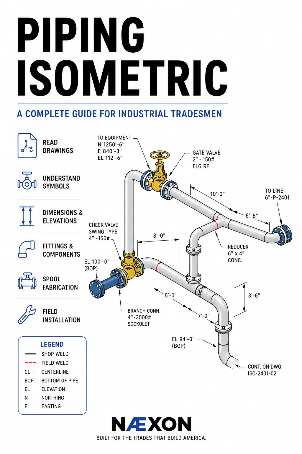
Piping isometric drawings are one of the most important documents used in industrial piping. Whether you are working in a refinery, chemical plant, power plant, fabrication shop, pipeline facility, or large industrial construction project, the ability to read an isometric can directly affect how accurately and efficiently you perform the work.
For pipefitters and welders especially, the isometric is often the drawing that turns engineering information into something that can actually be fabricated and installed. It tells the crew where the pipe goes, what components belong in the line, how those components are oriented, what size and specification the piping requires, and how the finished assembly connects to the rest of the system.
A complicated isometric can look intimidating when you first unfold it. Lines travel diagonally across the page. Elbows change direction. Dimensions appear in several locations. Weld numbers, elevations, coordinates, valve symbols, flange symbols, reducers, branch connections, and notes may all compete for attention.
The trick is not trying to understand the entire drawing at once.
Experienced hands break the ISO into pieces and follow the piping system one connection at a time.
What Is a Piping Isometric Drawing?
A piping isometric drawing, commonly called an ISO, is a three-dimensional representation of a piping system drawn on a two-dimensional sheet.
Unlike a plan drawing, which generally shows the piping from above, or an elevation drawing, which shows it from the side, an isometric drawing allows several directions of piping to be represented simultaneously.
The drawing normally uses three primary axes. Vertical piping is shown vertically, while the two horizontal directions are generally represented at approximately 30-degree angles from horizontal.
This creates the familiar three-dimensional appearance of an ISO.
An important thing to understand is that an isometric drawing is generally not drawn to scale.
A six-inch piece of pipe may appear longer on the page than a twenty-foot piece somewhere else on the same drawing. The graphical length of the line should never be used to determine the actual pipe length.
The written dimensions control.
That single rule prevents a lot of mistakes.
What Information Can Be Found on a Piping ISO?
A properly prepared piping isometric contains much more than the shape of the pipe.
Depending on the project and engineering standard, the drawing may identify the line number, pipe size, piping specification, material class, insulation requirements, elevations, coordinates, valves, fittings, flanges, reducers, branch connections, vents, drains, instruments, supports, field welds, shop welds, tie-ins, equipment connections, spool numbers, weld numbers and other fabrication information.
Think of the ISO as a set of instructions.
The lines tell you where the piping travels.
The symbols tell you what is installed in the piping.
The dimensions tell you where everything belongs.
The notes and specifications tell you what the system must be built from and how it must be assembled.
Understanding all four is what turns looking at an ISO into actually reading one.
Start With the Title Block
Before following a single piece of pipe, check the title block.
This is one of the easiest habits to develop and one of the easiest to ignore.
The title block normally identifies the project, drawing number, revision, line or system information and other drawing-control information.
Always verify the revision.
Industrial projects change constantly. Engineering may relocate equipment, change valve types, modify elevations, add supports, alter tie-in locations or revise dimensions after the original drawing has already been issued.
Building from an outdated revision can result in an entire spool being fabricated correctly according to the wrong drawing.
A perfect spool built from obsolete information is still wrong.
Understand the Line Number
The piping line number is essentially the identification tag for the piping system.
Different companies use different numbering systems, but a line designation may contain information such as:
Pipe size – service – system number – piping specification – insulation designation
For example, a fictional line number might look something like:
6”-P-2401-CS150-H
The exact meaning depends on the project’s line-numbering standard.
One section could identify the nominal pipe size. Another could identify the process service. Another could identify the system or sequence number. Another might reference the piping material specification.
Never assume that a line-number format means the same thing from one project to another. The project legend, piping specification and engineering standards establish the actual meaning.
Learn the Three Isometric Directions
Understanding direction is the foundation of reading an ISO.
Imagine standing at the center of the drawing.
Pipe traveling vertically represents elevation change. The two diagonal axes represent the horizontal plant directions.
Engineering drawings commonly reference directions such as:
North / South
East / West
Up / Down
Many drawings include a north arrow or orientation indicator.
This matters because a line traveling toward the upper-right corner of the page does not automatically mean the pipe physically travels northeast. The drawing’s directional reference determines what that line represents.
Follow the orientation shown on the drawing rather than judging direction purely by appearance.
Coordinates Tell You Where the Pipe Is
Industrial piping frequently uses plant coordinates to establish exact locations.
You may encounter coordinates identified as:
N — Northing
E — Easting
EL — Elevation
For example:
N 1250’-6”
E 840’-3”
EL 112’-6”
These coordinates establish a specific point within the project’s coordinate system.
This becomes extremely important when locating equipment, pipe racks, structural steel, tie-ins and penetrations.
A pipe can have the correct dimensions internally and still be installed in the wrong place if the starting coordinates are incorrect.
That is why experienced fitters establish a reliable reference before laying out the rest of the system.
Elevation Is One of the Most Important Numbers on the Drawing
Elevation tells you the vertical position of the piping.
But you must know what part of the pipe the elevation refers to.
Depending on the drawing standard, an elevation may reference the pipe centerline, bottom of pipe, top of pipe or another defined point.
Common abbreviations include:
CL — Centerline
BOP — Bottom of Pipe
TOP — Top of Pipe
Never automatically assume an elevation represents centerline.
For example, suppose a drawing gives a bottom-of-pipe elevation. If you mistakenly treat it as centerline elevation, the entire run may end up too low.
On large piping, that difference can be substantial.
Follow the Pipe From a Known Starting Point
One of the easiest ways to read a complicated ISO is to locate a known connection and work outward.
A good starting point might be an equipment nozzle, flange connection, existing tie-in, battery limit, continuation point or another clearly identified reference.
Suppose the ISO begins at:
P-101 Discharge Nozzle
Follow the pipe away from that nozzle.
You might mentally read the system like this:
Pump nozzle → flange → reducer → straight pipe → elbow → vertical rise → valve → horizontal run → branch connection → equipment nozzle.
Instead of seeing a page full of lines and symbols, you are now following the physical construction sequence of the piping.
That is much easier to understand.
Read Dimensions Carefully
Dimensions are where fabrication becomes real.
An ISO may contain dimensions between fittings, centerlines, equipment connections, branches and other reference points.
The most important question is:
What exactly is this dimension measuring?
A dimension might represent center-to-center, center-to-face, face-to-face, center-to-end, flange-face-to-flange-face or an overall reference dimension.
Those are not interchangeable.
Suppose the drawing shows 10’-0” from the centerline of one elbow to the centerline of another elbow.
That does not mean you cut a ten-foot piece of pipe.
The fitting takeouts must be accounted for.
For a simple center-to-center run:
Cut Length = Center-to-Center Dimension − Fitting Takeout A − Fitting Takeout B
If the center-to-center dimension is 120 inches and each fitting has a 6-inch center-to-end dimension:
120 − 6 − 6 = 108 inches
The theoretical straight-pipe cut length would therefore be:
108 inches
or
9’-0”
Actual fabrication must still follow the approved fitting dimensions, weld-gap requirements and project procedures.
Understand Fitting Takeout
Takeout is one of the most important concepts in pipe layout.
A fitting occupies part of the overall dimension.
If you simply cut pipe equal to the dimension shown between fitting centerlines, the assembly will be too long.
Consider a 90-degree elbow.
The centerline of the piping continues through an imaginary intersection point, but the physical elbow occupies space between that centerline intersection and the end of the fitting.
That distance must be removed from the straight-pipe calculation.
The same concept applies to elbows, tees, reducers, flanges and many other components.
Knowing where the ISO dimension begins and ends allows you to determine which fitting dimensions must be deducted.
90-Degree Elbows
A 90-degree elbow changes the piping direction by 90 degrees.
On an ISO, the elbow may look different depending on its orientation.
A horizontal-to-horizontal turn looks different from a horizontal-to-vertical turn, even though both may use the same type of elbow.
This is why memorizing the appearance of a symbol alone is not enough.
You must understand the piping direction entering and leaving the fitting.
For long-radius 90-degree elbows, the nominal center-to-end dimension is commonly based on:
1.5 × Nominal Pipe Size
For example, a nominal 6-inch long-radius 90 has a nominal center-to-end dimension of:
6 × 1.5 = 9 inches
Always verify actual fitting dimensions against the applicable standard and project requirements rather than treating a shortcut as a substitute for the specification.
45-Degree Elbows
A 45-degree elbow changes direction by 45 degrees and is commonly used for offsets.
Two 45s are frequently used when piping needs to move around structural steel, equipment, existing piping or another obstruction while continuing in the same general direction.
When reading a 45-degree offset, identify the true offset and the travel.
For a simple equal 45-degree offset:
Travel = Offset × √2
Since √2 is approximately 1.414:
Travel ≈ Offset × 1.414
If the required offset is 12 inches:
12 × 1.414 = 16.968 inches
The theoretical center-to-center travel is approximately:
16 31/32 inches
The actual pipe cut must then account for the appropriate fitting takeouts and fabrication requirements.
Rolling Offsets
Rolling offsets are where many new pipefitters begin struggling with isometrics.
A rolling offset occurs when the piping changes position in two perpendicular directions at the same time.
Instead of moving only horizontally or only vertically, the pipe may move north/south and up/down before reaching the next point.
The first step is determining the true offset.
If the two perpendicular offsets are A and B:
True Offset = √(A² + B²)
Suppose the pipe must move 12 inches horizontally and 16 inches vertically.
True Offset = √(12² + 16²)
True Offset = √(144 + 256)
True Offset = √400
True Offset = 20 inches
If that true offset is accomplished using equal 45-degree fittings:
Travel = 20 × 1.414
Travel ≈ 28.28 inches
That travel represents the theoretical centerline distance between the offset fittings. Fitting takeouts still have to be considered when calculating the actual straight pipe.
This is a good example of why understanding pipefitter math makes isometric drawings much easier to interpret.
Reducers
Reducers transition between different pipe sizes.
Two common types are:
Concentric reducers — the centerlines of the two pipe sizes remain aligned.
Eccentric reducers — one side remains flat while the centerline changes.
Eccentric reducer orientation is extremely important.
Depending on the system, the drawing may require:
Flat on Top — FOT
or
Flat on Bottom — FOB
This can be critical on pump suction piping and other process systems where improper orientation may create unwanted high or low points.
Never install an eccentric reducer based simply on what looks convenient.
Follow the ISO, P&ID, piping specification and engineering requirements.
Valves
An ISO may show gate valves, globe valves, ball valves, check valves, butterfly valves and specialty valves.
Do not stop after identifying the valve type.
Check the orientation.
Some valves can operate correctly in multiple orientations. Others have flow-direction requirements, installation restrictions or accessibility requirements.
Check valves are a good example. Many designs depend on correct flow direction, and some designs have orientation restrictions.
Look for a flow arrow on the valve body and compare it with the process flow shown by the drawing.
Valve handles, handwheels, gear operators and actuators may also require specific orientation to maintain operating access.
A valve can technically fit into the piping and still be installed incorrectly.
Flanges
Flanges appear constantly on industrial piping isometrics.
You may encounter weld-neck, slip-on, socket-weld, threaded, blind, lap-joint and specialty flanges.
Pay attention to flange type, pressure class, facing and orientation.
For certain connections, bolt-hole orientation or flange clocking can be critical.
A flange may need to match an equipment nozzle, valve or existing connection. Rotating it incorrectly during fabrication can create major problems during installation.
This is especially important on prefabricated spools.
A spool can have perfect dimensions but still be unusable because one flange was welded with the wrong bolt-hole rotation.
Branch Connections
Branches may be made using tees, reducing tees, weldolets, sockolets, threadolets, laterals or fabricated branch connections.
When reading the ISO, determine the branch size, run size, connection type and branch orientation.
A branch shown on the upper side of a pipe is not necessarily physically on top unless the drawing orientation confirms it.
Use the ISO axes and orientation references.
For critical branch locations, dimensions and coordinates should establish exactly where the connection belongs.
Weld Symbols and Weld Identification
Fabrication isometrics often distinguish between different weld locations.
Two particularly important categories are:
Shop welds
and
Field welds
Shop welds are generally completed during fabrication under controlled shop conditions.
Field welds are completed during installation.
Field welds may be intentionally located to allow adjustment during erection.
Depending on the project, welds may also carry identification numbers used for quality-control tracking, weld maps, welder identification, inspection, NDE and turnover documentation.
Do not assume every joint shown on an ISO should be welded in the fabrication shop.
The drawing and project fabrication plan determine where the spool should be broken.
Field-Fit Welds
A field-fit weld provides adjustment where exact installed dimensions cannot be guaranteed before erection.
Existing piping is a common example.
A spool may be fabricated with additional material at one end. Once the spool reaches the field, the actual position is measured, the excess material is trimmed and the final connection is fitted.
That extra material exists for a reason.
Cutting a field-fit piece to the theoretical finished dimension in the shop can eliminate the adjustment needed during installation.
Tie-Ins
Tie-ins connect new piping to existing piping or another defined system boundary.
They deserve special attention because existing conditions do not always perfectly match old drawings.
Before fabricating a critical tie-in spool, field verification may be required.
Depending on the job, this may involve checking flange face location, elevation, orientation, bolt-hole rotation, existing pipe centerline and surrounding obstructions.
A difference of even a small amount can create serious problems on rigid piping systems.
Spool Numbers
Large piping systems are often divided into fabrication spools.
Instead of constructing the entire ISO as one assembly, engineering or fabrication planning divides it into manageable sections.
Each spool may receive an identification such as:
SP-01
SP-02
SP-03
The spool breaks help determine where fabrication stops and field assembly begins.
When working from an ISO, make sure you know exactly which spool you are building.
It is possible to understand the piping system correctly and still fabricate the wrong portion of it.
Pipe Supports
Piping supports should never be treated as decoration on the drawing.
Supports control the position and movement of the piping system.
Depending on the service, you may encounter shoes, guides, anchors, hangers, spring supports, dummy legs, trunnions and structural attachments.
An anchor restricts movement at a defined location.
A guide generally controls lateral movement while permitting movement in another direction.
A shoe supports the pipe while maintaining the designed relationship between the pipe and supporting steel.
Thermal systems can be particularly sensitive to support placement.
Moving a support because another location seems easier can change how the piping expands, contracts and transfers load.
Continuation Symbols
A large piping system rarely fits on one ISO.
When the line continues onto another drawing, a continuation reference tells you where to go next.
The continuation may identify another drawing number, line reference or match point.
Never assume the pipe simply ends because the drawing ends.
Follow the continuation reference until you understand where the system connects.
P&ID vs. Piping Isometric
A P&ID and a piping isometric serve different purposes.
The P&ID primarily explains the process.
It shows relationships between equipment, piping, valves, instruments and control systems.
The ISO primarily explains the physical piping arrangement.
A simple way to remember the difference is:
P&ID = What the system does.
ISO = How the piping is physically built.
Good industrial tradesmen learn to use both.
The P&ID can help you understand why a valve, instrument, bypass or branch exists. The ISO helps you determine where that component physically belongs.
Specifications Matter as Much as Dimensions
Correct dimensions do not automatically mean correct piping.
Imagine fabricating a spool perfectly but using the wrong schedule pipe, wrong flange class or wrong material.
Dimensionally, the spool might be perfect.
Technically, it could be unusable.
The piping specification may control pipe material, wall thickness, fitting type, flange rating, gasket type, bolting, branch connections, valve requirements and other construction details.
This is why experienced tradesmen do not read only the dimensions.
They read the entire drawing package.
A Practical Way to Read Any ISO
When you receive an unfamiliar isometric, establish the drawing identity and revision first. Then locate the line number and determine the pipe size, service and piping specification.
Find the orientation reference.
Next, locate a known starting point such as an equipment nozzle, tie-in or continuation.
Follow the centerline through the system one component at a time.
Identify every fitting, flange, valve, reducer and branch as you encounter it.
Then begin checking dimensions.
Separate center-to-center dimensions from face-to-face and center-to-face dimensions. Check elevations and coordinates at direction changes.
Look for spool breaks, field welds and field-fit locations.
Check flange orientation.
Check reducer orientation.
Check valve direction.
Check branch orientation.
Check support locations.
Finally, follow the system to its ending connection or continuation point.
By the time you finish, you should be able to mentally visualize the piping assembly in three dimensions.
That is the real goal.
Build the Pipe in Your Head Before Building It in the Field
One of the biggest differences between simply reading dimensions and truly understanding an ISO is visualization.
Experienced fitters often mentally construct the spool before touching the pipe.
Start at the first connection.
Imagine the flange.
Imagine the pipe leaving it.
Imagine the first elbow.
Which direction does it turn?
How far does it travel?
Does it rise or fall?
Where is the valve?
Which direction does the branch leave?
Where is the next flange?
Where does the spool terminate?
Once you can rotate that assembly mentally, complicated drawings become much easier.
You are no longer looking at diagonal lines on paper.
You are looking at a pipe system.
Common Isometric Reading Mistakes
Many ISO mistakes come from reading too quickly rather than from difficult mathematics.
A fitter may confuse center-to-center with face-to-face dimensions, miss an elevation change, reverse an eccentric reducer, overlook a field weld, use the wrong revision, misread the north arrow or fabricate a flange with incorrect bolt-hole orientation.
Another common mistake is calculating every dimension independently without checking the overall geometry.
Good layout includes verification.
If several dimensions form an overall measurement, calculate the overall independently whenever possible. If coordinates are provided at both ends of a run, compare your calculated movement against the coordinate difference.
Redundant checks catch mistakes before steel gets cut.
The ISO Should Tell a Story
A piping isometric becomes much easier when you stop treating it as a collection of symbols.
It is a story about a pipe.
The pipe starts somewhere.
It travels in a particular direction.
It rises or falls.
It turns.
It changes size.
It passes through valves.
It branches.
It is supported.
It eventually reaches another piece of equipment, another piping system or another drawing.
Read that story from beginning to end.
Once you understand where the pipe begins, where it ends and what happens between those two points, most of the drawing begins to make sense.
Why Isometric Reading Is Such an Important Industrial Skill
A tradesman who can confidently read an ISO can do much more than follow instructions.
He can plan fabrication, calculate pipe lengths, recognize fitting orientations, identify potential installation problems, verify field conditions and communicate more effectively with welders, foremen, engineers, quality-control personnel and other trades.
The drawing stops being something that tells you what to do.
It becomes a tool you can use to understand the entire job.
That skill becomes especially valuable during shutdowns and turnarounds, where schedules are compressed and mistakes can quickly affect multiple crews.
A good pipefitter should eventually be able to look at an isometric, understand the piping path, calculate the required pieces and visualize how the spool will fit into the plant before fabrication begins.
That is when you have moved beyond simply reading an ISO.
You understand what you are building.
Næxon Learning Center — Built for the trades that build America.


