Structural steel can be incredibly forgiving right up until two pieces have to bolt together.
A beam can be cut correctly. A plate can be the right size. The steel can be square. But if a bolt pattern is laid out incorrectly by even a small amount, the connection may not fit. That is why experienced ironworkers and fabricators do not simply measure from one hole to the next and hope everything works out. They establish reference lines, work from centers, verify the overall pattern, and use basic geometry to make the layout repeatable.
Bolt-hole layout is not complicated mathematics. Most of it comes down to understanding centerlines, edge distance, gauge, pitch, hole diameter, overall dimensions, and equal spacing. Once those ideas make sense, a large bolt pattern becomes a series of simple measurements.
This guide explains the field math behind bolt-hole layout and, more importantly, how to think about the layout so mistakes are caught before the drill, mag drill, punch, or torch ever touches the steel.
Start With the Most Important Rule: Lay Out Centers
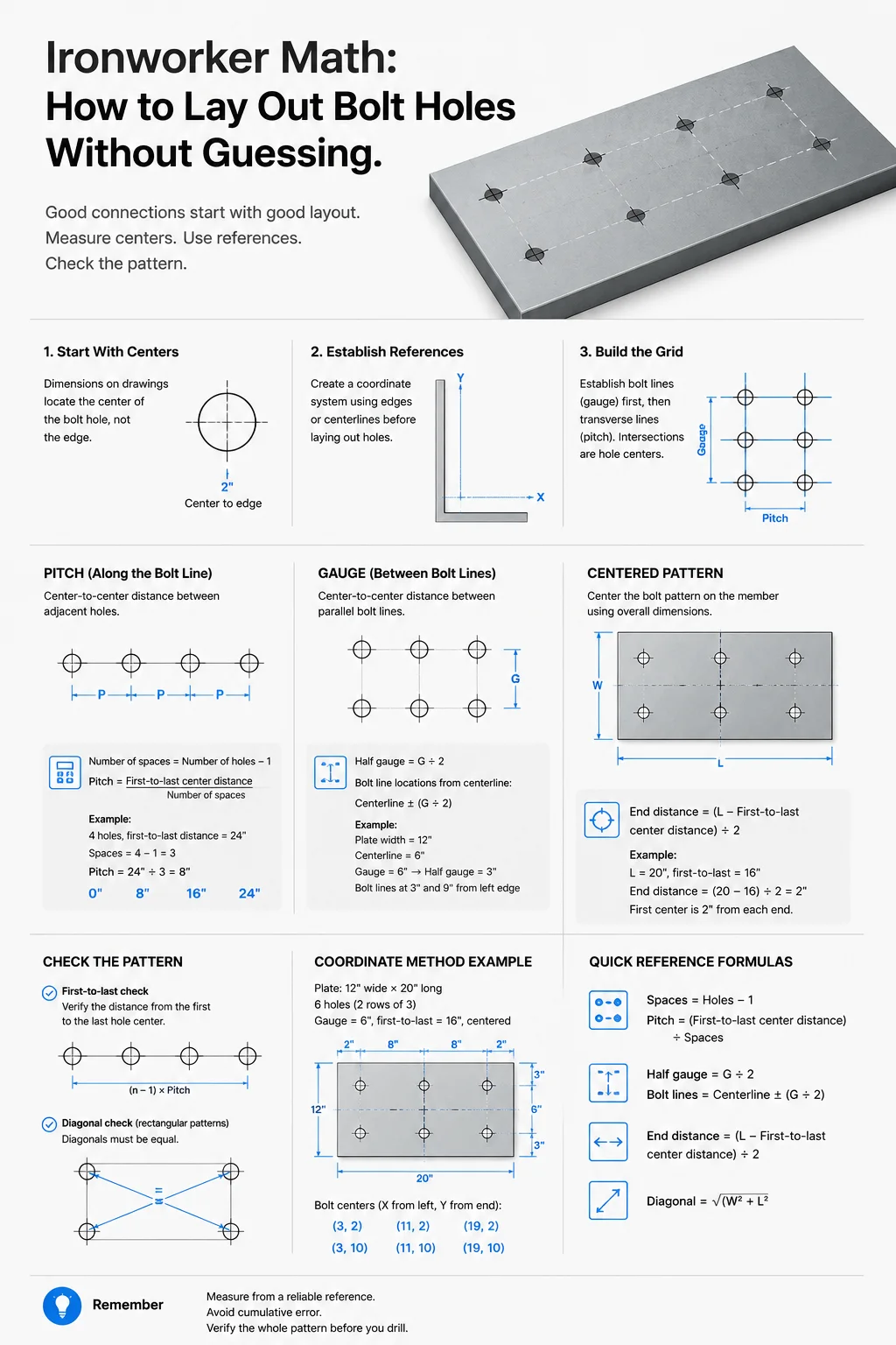
When an ironworker lays out a bolt hole, the important dimension is normally the center of the hole, not the outside edge of the hole.
That distinction matters.
Suppose a drawing shows a bolt center 2 inches from the edge of a plate. That does not mean the edge of the hole starts 2 inches from the plate edge. It means the centerline of the hole is 2 inches from the reference edge.
If the hole is 13/16 inch in diameter, half of that hole extends to each side of the center mark.
This is why center punching is so important. The punch mark represents the exact theoretical location of the bolt center. The hole is then produced around that point.
Think of every bolt pattern as a collection of points first.
The holes come later.
That same centerline thinking is used throughout industrial layout. It is similar to the principles used when finding pipe centerlines, establishing equipment centerlines, laying out anchor bolts, and reading structural drawings. Understanding centerlines is one of the most transferable layout skills a tradesman can develop.
Establish a Reference Before Measuring Anything
One of the easiest ways to create a bad bolt pattern is to start measuring holes before establishing where the pattern itself belongs.
Every layout needs a reliable reference.
That reference might be the edge of a plate, the end of a beam, the centerline of a member, a work point shown on the drawing, or another established datum.
Suppose you have a rectangular plate measuring:
12 inches wide × 18 inches long
and the drawing requires four bolt holes positioned 2 inches from every edge.
Do not immediately start marking individual holes.
First establish the two layout lines running parallel to the long edges:
2 inches from the left edge
and
2 inches from the right edge.
Then establish the transverse lines:
2 inches from the top
and
2 inches from the bottom.
Where those lines intersect are the four bolt centers.
That approach is much more reliable than trying to locate every hole independently.
You are essentially building a coordinate system on the steel.
Edge Distance
Edge distance is the distance from the center of a bolt hole to the edge of the material.
If a drawing specifies:
Edge distance = 2”
your hole center is marked 2 inches from that edge.
This measurement is important structurally because there must be sufficient steel between the hole and the edge of the member. Too little material can contribute to bearing, tear-out, or other connection problems.
Do not assume an edge distance just because a measurement “looks normal.” Structural connections are engineered, and the drawing, approved detail, project specification, and applicable code requirements control the actual layout.
As a useful concept, minimum bolt spacing and edge distances are related to bolt diameter, hole type, material geometry, and connection design. They are not arbitrary numbers that should be changed in the field simply to make a connection fit.
Pitch: The Distance Along the Bolt Line
Pitch is the center-to-center distance between consecutive bolts along the direction of the bolt line.
Imagine four holes in a straight row:
O —— O —— O —— O
If every center is 3 inches apart, the pitch is:
3 inches
But there is an important detail here.
Four holes do not create four spaces.
They create three spaces.
That gives us one of the most useful bolt-layout rules:
Number of spaces = Number of holes − 1
For four holes:
4 − 1 = 3 spaces
For six holes:
6 − 1 = 5 spaces
For ten holes:
10 − 1 = 9 spaces
This becomes extremely useful when the drawing gives you the overall distance between the first and last bolt centers instead of the individual spacing.
Calculating Equal Bolt Spacing
Suppose the distance from the center of the first hole to the center of the last hole is:
24 inches
You need:
5 equally spaced holes
First determine the number of spaces:
5 − 1 = 4 spaces
Now divide the overall center-to-center distance by the number of spaces:
24 ÷ 4 = 6 inches
Therefore:
Pitch = 6 inches
The bolt centers are located at:
0” — 6” — 12” — 18” — 24”
This formula is worth remembering:
Pitch = Distance between first and last hole centers ÷ (Number of holes − 1)
This same principle works whether you are laying out a small clip angle or a long structural plate.
Gauge: The Distance Across Bolt Lines
If pitch describes spacing along a bolt line, gauge generally describes the transverse center-to-center spacing between parallel bolt lines.
Imagine two rows:
O —— O —— O
O —— O —— O
The horizontal distance between holes may be the pitch.
The perpendicular distance between the two rows is the gauge.
Suppose the gauge is:
4 inches
You could establish one bolt line, measure exactly 4 inches perpendicular to it, and establish the second bolt line.
Once the two lines are established, the pitch measurements locate the individual hole centers.
Instead of locating six holes separately, you are creating a grid.
That is the key idea.
The Grid Method
One of the cleanest ways to lay out multiple bolt holes is to stop thinking about individual holes altogether.
Think about lines.
Suppose a plate requires eight holes arranged as two rows of four.
The drawing specifies:
Edge distance from each side = 2”
End distance = 2”
Gauge = 6”
Pitch = 3”
Start by establishing the first longitudinal bolt line.
Then establish the second longitudinal line exactly 6 inches away.
Now establish the first transverse bolt line 2 inches from the end.
From that line, mark additional transverse lines every 3 inches.
Every intersection becomes a hole center.
Instead of measuring eight independent locations, you have created two longitudinal lines and four transverse lines.
The geometry creates the bolt pattern for you.
This method also makes mistakes much easier to see because one crooked or incorrectly spaced line affects the visible grid.
Using the Centerline of the Steel
Sometimes the drawing gives dimensions from the centerline rather than from the edges.
Suppose a plate is:
10 inches wide
The centerline is:
10 ÷ 2 = 5 inches
Now suppose two bolt rows need to be 6 inches apart.
Half the gauge is:
6 ÷ 2 = 3 inches
Measure 3 inches to each side of the plate centerline.
That places the bolt lines at:
2 inches from one edge
and
8 inches from the same edge.
This is an extremely useful method because symmetrical bolt patterns can be laid out from a single centerline.
The formula is simple:
Half gauge = Gauge ÷ 2
Then:
Bolt-line location = Centerline ± Half gauge
This prevents accumulated measurement errors and makes symmetry easy to verify.
A Complete Field Example
Imagine you have a plate that is:
12” wide × 20” long
The drawing calls for six bolt holes arranged in two rows of three.
The bolt rows have a:
6” gauge
The first and last bolt centers are:
16” apart
The pattern is centered on the plate.
Start with the width.
The plate is 12 inches wide, so its centerline is:
12 ÷ 2 = 6”
The gauge is 6 inches.
Half the gauge is:
6 ÷ 2 = 3”
Therefore the two bolt lines are:
6 − 3 = 3”
and
6 + 3 = 9”
measured from the same side of the plate.
Now calculate the pitch.
There are three holes in each row.
Three holes create:
3 − 1 = 2 spaces
The distance between the first and last centers is 16 inches.
Therefore:
16 ÷ 2 = 8” pitch
The bolt locations along each row are therefore:
First hole: 0”
Second hole: 8”
Third hole: 16”
relative to the first bolt center.
If the entire 16-inch pattern is centered along the 20-inch plate, there are:
20 − 16 = 4”
remaining.
Divide that equally between both ends:
4 ÷ 2 = 2”
So the first bolt center is 2 inches from one end and the last bolt center is 2 inches from the opposite end.
Your finished coordinates measured from one corner are:
3”, 2”
3”, 10”
3”, 18”
and
9”, 2”
9”, 10”
9”, 18”
That is the entire six-hole pattern calculated before a single hole is made.
The Difference Between Bolt Diameter and Hole Diameter
A common beginner mistake is assuming that a 3/4-inch bolt automatically goes into a 3/4-inch hole.
Structural bolt holes normally provide clearance around the bolt. The required hole size depends on the fastener diameter and whether the connection uses standard, oversized, short-slotted, or long-slotted holes.
For example, under common structural-steel provisions, a standard hole for a 3/4-inch bolt is typically 13/16 inch, while a standard hole for a 1-inch bolt is typically 1-1/8 inches.
But this is not permission to choose a hole size in the field.
Always use the hole type and dimensions specified by the approved drawings, fabrication details, project requirements, and governing specification. Oversized and slotted holes have additional design considerations, and changing a hole is not simply a fabrication convenience.
The important layout lesson is:
Bolt diameter and hole diameter are two different dimensions.
A Quick Spacing Rule — And Why It Is Not a Substitute for the Drawing
Structural-steel specifications establish minimum spacing requirements for bolts. A commonly encountered design relationship is that center-to-center spacing cannot simply be made arbitrarily tight; approximately 3 bolt diameters center-to-center is a commonly preferred spacing, although actual minimum requirements and connection-specific limits must be checked.
For a 3/4-inch bolt:
3 × 3/4” = 2-1/4”
That gives you useful intuition about the scale of a typical bolt pattern.
But an ironworker should never use a rule of thumb to override an engineered dimension.
Rules of thumb help you recognize something that looks suspicious.
Drawings determine what you actually build.
How to Divide an Odd Dimension Into Equal Spaces
This is where field fractions become important.
Suppose the first-to-last bolt-center distance is:
17-1/4 inches
and you need four holes.
Four holes create:
4 − 1 = 3 spaces
Therefore:
17-1/4 ÷ 3
Convert the fraction:
17-1/4 = 17.25
Then:
17.25 ÷ 3 = 5.75
Convert back to a fraction:
5.75 = 5-3/4”
Your pitch is:
5-3/4 inches
Check it:
5-3/4 × 3 = 17-1/4”
That last step is important.
Always work the calculation backward before committing to the steel.
Running Dimensions Can Reduce Error
Suppose you need five holes at 3-1/2-inch pitch.
You could measure 3-1/2 inches from one hole to the next repeatedly.
But every new measurement introduces another opportunity for error.
A better approach is often to measure every hole from the same established reference.
The running dimensions would be:
First center = 0”
Second = 3-1/2”
Third = 7”
Fourth = 10-1/2”
Fifth = 14”
Now every location comes from the same datum.
This prevents a small mistake at hole number two from shifting holes three, four, and five.
That principle is known as avoiding cumulative error.
It applies far beyond ironwork. The same thinking is valuable when laying out pipe supports, equipment, structural attachments, and other repetitive industrial work.
The First-to-Last-Hole Check
Before making the holes, verify the overall dimension.
If there are five holes with a 4-inch pitch, there are four spaces.
Therefore:
4 spaces × 4” = 16”
The distance from the center of the first hole to the center of the fifth hole must be:
16 inches
If you measure something different, stop.
Something in the layout is wrong.
Checking only individual spaces can allow a mistake to hide. Checking the overall pattern gives you an independent verification.
A good layout should satisfy both:
Individual spacing
and
Overall spacing
before fabrication begins.
Check the Diagonals on Rectangular Patterns
There is another powerful verification method when four or more holes form a rectangle.
Measure diagonally from one corner hole center to the opposite corner hole center.
Then measure the other diagonal.
For a true rectangular pattern, those diagonal measurements should match.
If one diagonal is longer than the other, the bolt pattern may be racked or out of square even if some of the individual dimensions appear correct.
This uses the same geometry behind checking whether a rectangular frame is square.
For a rectangular bolt pattern with width W and length L, the theoretical diagonal can also be calculated using the Pythagorean theorem:
Diagonal = √(W² + L²)
For example, if the bolt pattern is:
6” wide × 8” long
then:
Diagonal = √(6² + 8²)
Diagonal = √(36 + 64)
Diagonal = √100
Diagonal = 10”
Both diagonals should therefore measure 10 inches.
This is one reason basic trade geometry matters so much. The same triangle mathematics used in structural layout also appears constantly in pipe offsets, rigging, fabrication, equipment setting, and construction surveying.
The Two-Tape Method
On larger work, another practical way to locate a point is to measure from two established references.
Imagine a hole center must be:
10 inches from Point A
and
8 inches from Point B.
Swing one tape or radius from Point A and another from Point B.
Where the two measurements intersect is the required point.
Geometrically, you are locating the intersection of two circles.
This principle becomes extremely useful when laying out large plates, anchor bolts, structural assemblies, equipment bases, and locations where measuring square from an edge is difficult.
It is essentially field triangulation.
Why Measuring From Hole to Hole Can Get You in Trouble
Imagine you need eight holes spaced exactly 3 inches apart.
You mark the first hole.
Then measure 3 inches from that mark for the second.
Then another 3 inches from the second for the third.
Then another 3 inches.
If every measurement is off by only 1/32 inch in the same direction, the accumulated error grows as you move down the pattern.
A few holes may still look fine.
The final hole may not.
Instead, establish one reference and use running dimensions:
3”
6”
9”
12”
15”
18”
21”
Now every hole is independently related to the original datum.
The pattern cannot slowly “walk” away because of repeated small measuring errors.
Center Punching Matters
After the layout is complete, the intersection of your layout lines needs to survive the fabrication process.
That is where the center punch comes in.
A good punch mark creates a physical reference that remains after soapstone, marker, or layout fluid becomes difficult to see.
But the punch does not fix bad layout.
Before punching, verify:
the reference edge,
the bolt-line location,
the pitch,
the gauge,
the first-to-last dimension,
and the overall squareness of the pattern.
Once the pattern checks, punch the intersections.
The goal is to make the punch mark the final confirmation of the layout, not the beginning of it.
Never “Fix” Engineered Bolt Holes Without Authorization
One of the most important lessons in structural work is knowing where field judgment stops.
If holes do not align during erection, the solution is not automatically to enlarge them, slot them, burn them, ream them excessively, or move the connection.
Misalignment may indicate a fabrication problem, erection problem, dimensional problem, incorrect member, incorrect orientation, or drawing discrepancy.
Structural bolt holes are part of an engineered connection.
Changing their geometry can change how the connection behaves.
The right response is to identify why the connection does not fit and follow the project’s approved procedure for resolving the discrepancy.
A good ironworker knows how to make steel fit.
A great ironworker also knows when not to modify it.
A Simple Bolt-Layout Workflow
For most basic patterns, the process can be reduced to one sequence:
Establish the datum → establish centerlines → locate bolt lines → calculate pitch → mark running dimensions → verify overall dimensions → check square/diagonals → center punch → verify again → make the holes.
Notice how far down the sequence drilling actually occurs.
Most of the quality of the finished connection is determined before the tool ever starts cutting.
The Math Worth Memorizing
You do not need dozens of formulas for ordinary bolt-hole layout. A handful will handle a surprising amount of field work.
For equal spacing:
Number of spaces = Number of holes − 1
Pitch = First-to-last center distance ÷ Number of spaces
For a centered pattern:
Centerline = Overall width ÷ 2
Half gauge = Gauge ÷ 2
Bolt lines = Centerline ± Half gauge
For checking a rectangular pattern:
Diagonal = √(Length² + Width²)
For a centered first-to-last pattern:
End distance = (Overall length − First-to-last center distance) ÷ 2
These formulas are simple enough to perform with a tape measure and calculator, but understanding what they represent is more valuable than simply memorizing them.
Learn to See the Geometry Before You See the Holes
The biggest improvement an ironworker can make in bolt-hole layout is changing the way the pattern is visualized.
Do not see six holes.
See two bolt lines crossed by three pitch lines.
Do not see twelve holes.
See three bolt lines crossed by four pitch lines.
Do not see four corner holes.
See a rectangle that can be checked with two diagonals.
Once you begin thinking this way, complicated-looking patterns become much easier.
The steel becomes a coordinate system.
The bolt centers become intersections.
And the layout becomes geometry instead of guesswork.
That same mindset carries directly into other Næxon Learning Center subjects such as structural steel erection drawings, anchor-bolt layout, trade geometry, rigging calculations, pipefitter math, and reading industrial drawings. The trades may use different tools and terminology, but the underlying skill is the same: establish a trustworthy reference, calculate from that reference, and verify the result before making a permanent move.
Measure the Pattern, Not Just the Holes
A beginner often asks, “Is this hole in the right place?”
An experienced hand asks a bigger question:
“Is the entire pattern right?”
That difference matters.
One correctly located hole does not guarantee a correct connection. The pitch can be wrong. The gauge can be wrong. The pattern can be shifted. The rectangle can be out of square. The overall dimension can be wrong even though several individual measurements appear correct.
That is why good structural layout uses multiple checks.
Measure the hole location.
Check the pitch.
Check the gauge.
Check the first-to-last dimension.
Check the relationship to the member centerline.
Check the diagonals when applicable.
Then make the hole.
There is nothing impressive about drilling eight holes quickly if the connecting steel cannot bolt up.
The real skill is making eight holes once—and having the steel fit when it arrives.


