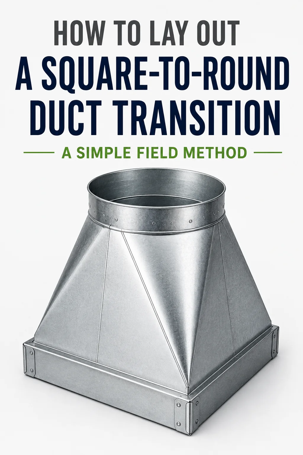
A square-to-round transition looks complicated until you break it into what it really is: a square opening changing gradually into a circular opening.
This type of transition is common in HVAC ductwork, industrial ventilation, dust collection, exhaust systems, equipment connections, and fabrication shops. One end has four straight sides. The other end has a circumference. The fabricator’s job is to connect those two different shapes smoothly while keeping the dimensions correct.
There are several ways to develop a square-to-round transition. For precision sheet-metal fabrication, especially when a true flat pattern is required, triangulation is the standard geometric method. But before getting deep into development geometry, it helps to understand the simplest practical method: divide the round end into equal sections, establish corresponding points on the square end, connect those points, and determine the true lengths needed to create the pattern.
Once you understand that principle, the transition stops looking complicated.
First Understand the Shape
Imagine a square duct sitting vertically.
At the bottom you have a square opening.
At the top you have a round opening.
For a simple centered transition, the center of the round is directly over the center of the square.
If the transition is 12 inches tall, every point on the round opening is 12 inches vertically above the plane of the square opening.
But those points are not all the same horizontal distance from the square’s edges and corners.
That is why simply measuring the transition height and drawing straight lines will not produce an accurate flat pattern.
Some sections of the sheet must travel farther than others.
The corners are especially important.
This is where triangulation comes in.
Example We Will Use
To make the process easy to follow, imagine we need a centered transition with:
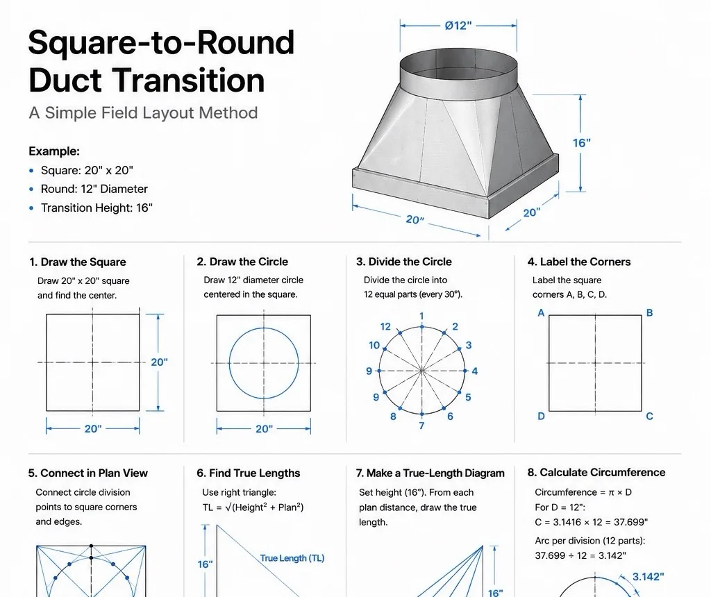
Square opening: 20” × 20”
Round opening: 12” diameter
Transition height: 16”
Those three dimensions define the basic shape.
Before laying anything out, verify whether the transition is centered or offset. An offset square-to-round transition requires additional geometry because the centers of the two openings are no longer directly aligned.
For this lesson, we will keep everything centered.
Step 1: Draw the Square Opening
Start with a plan view.
Draw a:
20” × 20” square
Then establish the center by drawing the two centerlines.
Because the square is 20 inches wide:
20 ÷ 2 = 10”
The center is therefore 10 inches from every side.
That center point becomes the center of the round opening as well.
Establishing centerlines first is one of the most important habits in fabrication. It is the same principle used throughout the Næxon Learning Center in lessons such as Ironworker Math: How to Lay Out Bolt Holes Without Guessing, Flange Bolt-Hole Rotation and Clocking, and How to Calculate Flange Bolt Circle Diameter and Hole Spacing.
Good layout begins with a trustworthy reference.
Step 2: Draw the Round Opening
The round opening is:
12” diameter
Its radius is:
12 ÷ 2 = 6”
Set a compass to 6 inches and draw the circle from the center of the square.
You now have a 12-inch circle centered inside a 20-inch square.
This plan view represents the relationship between the two ends of the transition.
Do not think about sheet metal yet.
Think about geometry.
Step 3: Divide the Circle Into Equal Sections
The round end must be divided into equal sections so you have known points to connect back to the square.
A simple transition can be developed using:
12 equal divisions
More divisions generally create a more refined development because the round opening is represented by more points.
A circle contains:
360°
For 12 divisions:
360 ÷ 12 = 30°
So place a point every:
30 degrees
around the circle.
Label the points sequentially:
1, 2, 3, 4, 5, 6…
until all 12 divisions are identified.
This is the same circular geometry used when laying out bolt circles and dividing pipe circumference.
Step 4: Understand Why the Circle Is Divided
Those points are not just marks.
Each point represents a location on the round end that must connect to a corresponding location on the square end.
Imagine stretching straight wires from the square opening to the round opening.
Each wire would represent one line across the finished transition.
Some wires would be shorter.
Some would be longer.
If you could measure the true length of every one of those wires, you could transfer those measurements onto flat sheet and reproduce the transition.
That is essentially what triangulation does.
It converts a three-dimensional transition into measurable triangles.
Step 5: Establish the Square Corners
Label the four corners of the square:
A
B
C
D
Now you have two sets of references.
The square has:
A–B–C–D
The circle has:
1–12
The development is created by determining the relationships between those points.
Because this is a centered and symmetrical transition, much of the geometry repeats.
That symmetry saves a considerable amount of layout work.
Step 6: Draw the Triangulation Lines in Plan View
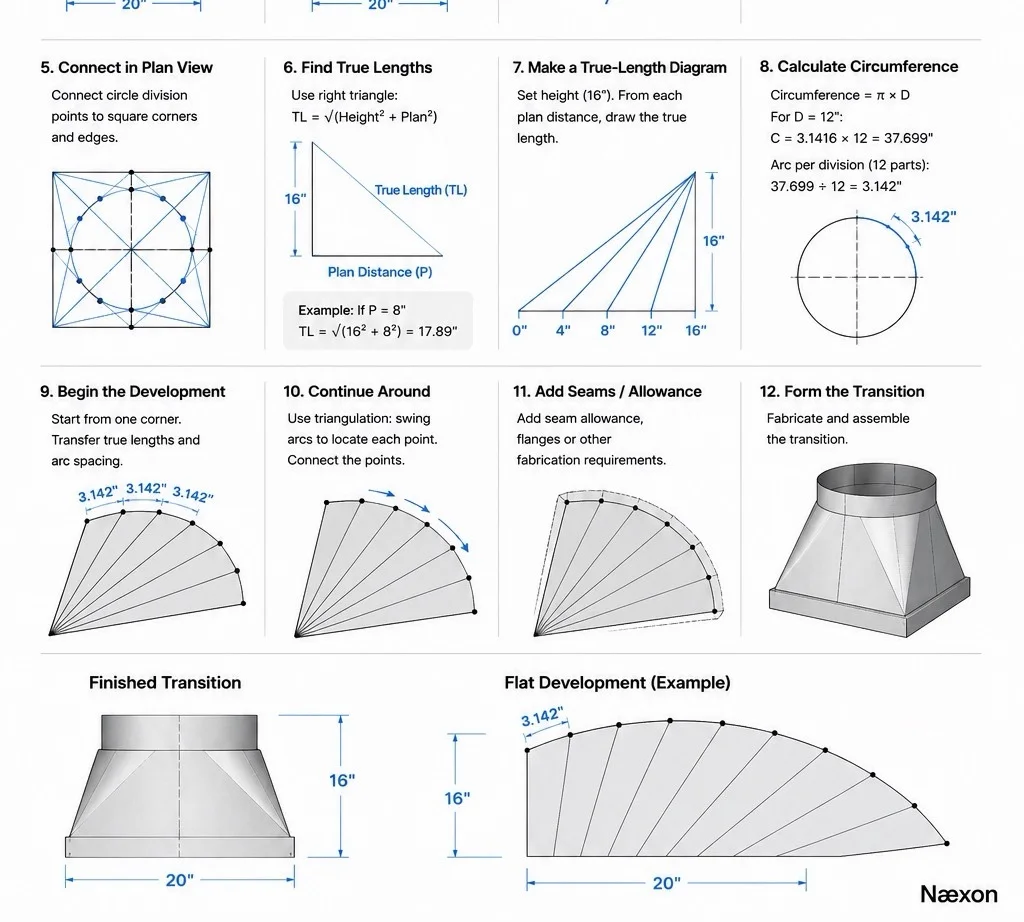
Now connect the appropriate circular division points back to the square corners and edges.
This creates a series of triangles in the plan view.
These lines represent the horizontal component of the transition surfaces.
The important thing to understand is that the plan-view line is not yet the actual sloping length of the sheet.
It only shows how far the connection travels horizontally.
The transition also rises:
16 inches
So the actual surface line must travel both:
horizontally
and
vertically
That creates a right triangle.
Now we can use the same basic geometry that appears throughout pipefitting, structural layout, rigging, and fabrication.
Step 7: Find the True Length
Suppose one plan-view connection measures:
8 inches
The transition height is:
16 inches
The actual sloping surface line becomes the hypotenuse of a right triangle.
Use:
True Length = √(Height² + Plan Distance²)
Therefore:
TL = √(16² + 8²)
TL = √(256 + 64)
TL = √320
TL ≈ 17.89”
So even though the transition is only 16 inches tall, that particular sheet line must actually travel approximately:
17.89 inches
This is why using transition height alone will produce the wrong development.
The sheet travels diagonally.
Step 8: Why Different Points Have Different True Lengths
Consider another point whose plan distance is:
11 inches
Using the same 16-inch transition height:
TL = √(16² + 11²)
TL = √(256 + 121)
TL = √377
TL ≈ 19.42”
The first line was approximately:
17.89”
The second is approximately:
19.42”
That difference is what creates the changing shape of the transition.
The sheet near a square corner generally has to develop differently from the sheet near the middle of a side.
If every line were laid out at the same length, you would not get a proper square-to-round transition.
Step 9: Make a True-Length Diagram
Rather than calculating every sloping line separately with a calculator, fabricators often create a true-length diagram.
Draw a horizontal baseline.
From one end, draw a vertical line equal to the transition height:
16”
Along the baseline, mark the different plan distances obtained from your plan view.
For each plan distance, connect that point to the top of the 16-inch vertical line.
The resulting diagonal is the true length.
This creates a visual reference from which the required lengths can be transferred with dividers.
The geometry is simply the Pythagorean theorem drawn full-size.
The Næxon Learning Center’s Pipefitter Math and How to Calculate Pipe Travel, Run, and Set for Any Offset lessons use the same underlying relationship: when two perpendicular dimensions are known, the diagonal can be calculated or constructed.
Step 10: Calculate the Round-End Division Spacing
Eventually the round opening has to be represented on flat sheet.
For a 12-inch diameter round:
Circumference = π × Diameter
Therefore:
C = 3.1416 × 12
C ≈ 37.699”
If the circle is divided into 12 equal sections:
37.699 ÷ 12 ≈ 3.142”
So each division represents approximately:
3.142 inches of arc length
around the finished round opening.
There is an important distinction here.
That 3.142-inch measurement is an arc distance around the finished circle. A precise geometric development may instead use chord-based construction between division points depending on the method being used.
Understanding the difference between an arc and a chord is also covered in How to Calculate Flange Bolt Circle Diameter and Hole Spacing.
Step 11: Begin the Flat Development
Now the three-dimensional transition can begin to unfold onto flat sheet.
Establish the starting edge of the development.
From that reference, use the appropriate round-division spacing and the true lengths you established during triangulation.
Each new point is located from known points.
Think of the process as building triangles one at a time.
You know one side from the round division.
You know another relationship from the square end.
You know the required true length from the true-length diagram.
Swing arcs from the established points.
Where the arcs intersect gives you the next point in the development.
Then repeat.
This is why the method is called:
triangulation.
You are not trying to draw a curved transition by eye.
You are constructing a chain of mathematically controlled triangles.
Step 12: Connect the Points Smoothly
Once all the points have been transferred to the flat development, connect the appropriate points.
The square-end portions will follow the required straight geometry.
The round-end development will appear as a series of points.
Do not aggressively connect those round points with sharp corners unless the fabrication method specifically requires segmented facets.
Instead, establish the required smooth transition line through the points.
Those points collectively represent the round opening when the sheet is formed.
The more divisions used during development, the more accurately the layout represents the circle.
Step 13: Add Seams and Allowances After the Geometry Is Correct
The geometric development represents the finished transition dimensions.
Fabrication still requires allowances.
Depending on the construction method, you may need additional material for:
longitudinal seams,
locks,
flanges,
slip connections,
weld seams,
or other joining methods.
These allowances should be added after the finished geometry has been established.
Do not mix seam allowance dimensions into your basic geometric calculations.
First develop the finished shape.
Then add what fabrication requires.
This keeps the layout understandable and prevents seam dimensions from accidentally changing the actual duct size.
The Simple Way to Think About the Entire Process
If all of the geometry feels complicated, reduce the transition to four ideas.
Square.
Circle.
Height.
Triangles.
Draw the square.
Center the circle.
Divide the circle.
Connect known points.
Find the true length of the connecting lines using the transition height.
Transfer those true lengths onto flat sheet.
That is the foundation of the entire development.
A Useful True-Length Formula
For a centered transition, whenever you know the horizontal plan distance between two corresponding points and the vertical transition height, the true length is:
TL = √(H² + P²)
where:
TL = True Length
H = Transition Height
P = Plan Distance
Example:
Height = 18”
Plan distance = 7”
Then:
TL = √(18² + 7²)
TL = √(324 + 49)
TL = √373
TL ≈ 19.31”
That one formula explains much of what is happening geometrically.
Why a Taller Transition Is Usually Easier to Fabricate
Suppose you need to transition from a large square opening to a much smaller round opening.
If the transition is very short, the sheet must change direction aggressively.
That creates steeper sides and can make forming more difficult.
Increasing the transition height spreads the change over a greater distance.
The transition becomes more gradual.
This does not mean you can arbitrarily increase the height. Available space, airflow requirements, equipment geometry, drawings, and project specifications still control the installation.
But geometrically, a longer transition generally produces gentler slopes.
This is important in both fabrication and duct-system design.
Centered vs. Offset Square-to-Round Transitions
Everything in this lesson assumes the round opening is centered over the square opening.
An offset transition is different.
If the round moves toward one side, one end, or both, the plan distances change.
One side becomes steeper.
The opposite side becomes flatter.
The triangulation method still works.
That is one of its greatest advantages.
You simply establish the actual position of the round opening in plan view and calculate the true lengths from those real locations.
The geometry handles the offset automatically.
Do Not Guess the Round Location
A surprisingly small centerline error can create noticeable problems at installation.
Before beginning the development, verify:
square dimensions,
round diameter,
transition height,
and
center-to-center relationship between the two openings.
If the round is supposed to be centered, establish that mathematically.
For a 20-inch square:
Center = 20 ÷ 2 = 10”
For a 24-inch by 18-inch rectangle:
Long-direction center:
24 ÷ 2 = 12”
Short-direction center:
18 ÷ 2 = 9”
Their intersection is the center of the rectangular opening.
Place the center of the round relative to that point according to the drawing.
This is another example of why centerline thinking is so valuable across the industrial trades.
Check the Development Before Cutting
A good layout should be checked before any permanent cut is made.
Verify the square-end dimensions.
Verify the round diameter.
Verify the circumference calculation.
Verify the number of round divisions.
Verify the transition height used in the true-length construction.
Verify that the correct true lengths were transferred to the correct points.
Verify seam and connection allowances separately.
One incorrect transferred dimension can distort an entire section of the transition.
The time to discover that error is while the lines are still drawn on the sheet—not after the material has been cut and formed.
The Most Common Beginner Mistake
The biggest mistake is trying to visualize the finished transition while laying out the flat sheet.
That can become confusing very quickly.
Instead, separate the job into views.
The plan view tells you where the square and circle are located relative to one another.
The elevation gives you the transition height.
The true-length construction tells you how long the sloping lines actually are.
The development tells you what must be cut from the flat sheet.
Each drawing has one job.
Do not ask one view to tell you everything.
From Three Dimensions Back to Flat Sheet
The real skill in sheet-metal development is learning to move mentally between a finished three-dimensional object and a flat piece of material.
The finished transition may look complex.
The flat development may look even stranger.
But both are controlled by the same reference points.
The square corners remain square corners.
The round division points remain round division points.
The height remains constant on a centered level transition.
Triangulation simply tells you the true distance between those known locations.
Once you understand that, square-to-round development becomes much less mysterious.
The Field Logic Worth Remembering
When you encounter a square-to-round transition, remember this sequence:
Establish the square → find its center → locate the round → divide the circle → connect the reference points in plan → determine the true lengths → develop the triangles → verify the pattern → add fabrication allowances → cut and form.
Do not start with the sheet.
Start with the geometry.
That principle applies throughout fabrication. It is the same reason good pipefitters establish centerlines before calculating offsets, good ironworkers establish datums before laying out bolt holes, and good fabricators verify dimensions before making permanent cuts.
A square-to-round transition is not a shape you have to guess.
It is a collection of triangles.
Once you can find those triangles and determine their true lengths, you can build the transition.


