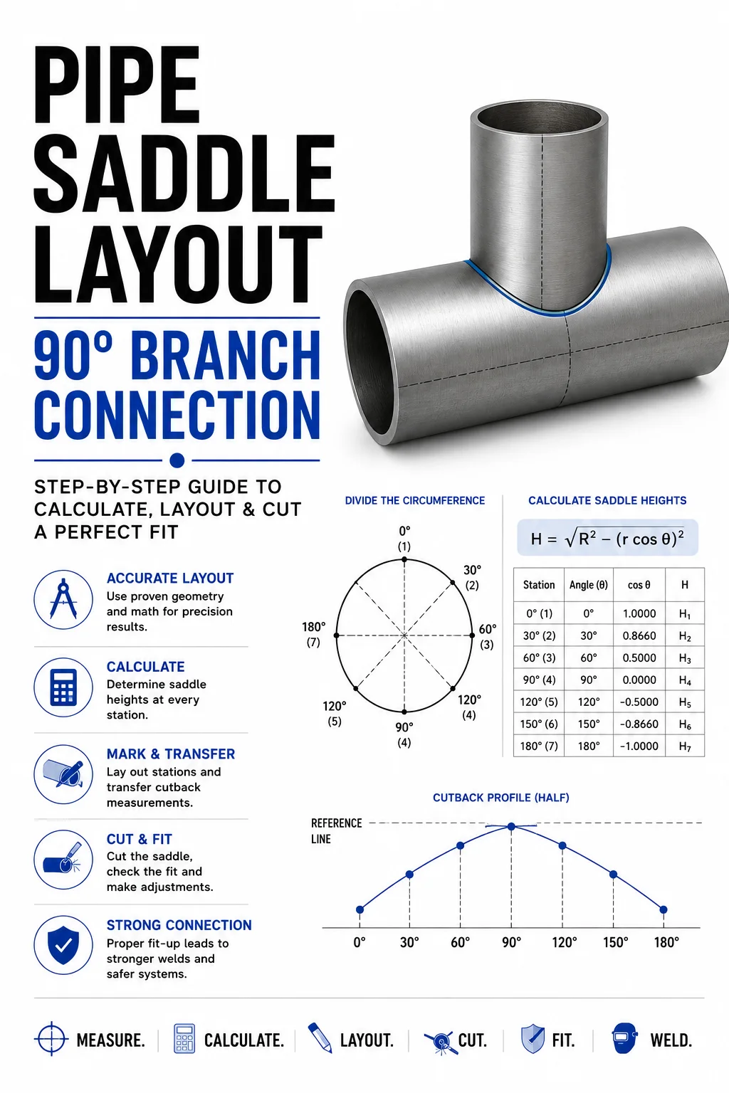
A branch connection looks simple when it is finished: one pipe intersects another, the branch end is cut to match the curvature of the main pipe, and the joint is welded together.
Getting that fit right is where the skill comes in.
A properly developed pipe saddle—often called a fishmouth—is not just a curved cut made by eye. The shape comes directly from the geometry created when two cylindrical surfaces intersect. If you understand that geometry, you can calculate and lay out the saddle instead of repeatedly cutting, grinding, checking, and grinding again.
The layout shown in the accompanying example uses the classic field-development method: divide the circumference into equal sections, calculate the required saddle height at each section, transfer those measurements onto the branch pipe, and connect the points into a smooth cutting line.
This article explains not only how to do it, but why the math works.
What Is a Pipe Saddle?
A pipe saddle is the contoured end of a branch pipe that allows it to fit against the outside diameter of another pipe.
Imagine placing the square-cut end of a smaller pipe against the side of a larger pipe. The center of the branch touches first, while gaps remain along other portions of the circumference.
Material therefore has to be removed from the branch.
Once correctly developed, the end of the branch follows the curvature of the run pipe.
The resulting profile is the saddle.
For pipefitters and fabricators, understanding saddle development is valuable because the same basic principles appear throughout industrial layout: branch connections, structural pipe intersections, headers, laterals and other cylindrical developments.
Start With the Actual Geometry
Before laying anything out, identify the dimensions that actually control the intersection.
For a basic 90° branch, you need the outside diameter of the run pipe and the outside diameter of the branch pipe.
From those, determine the radii:
R = run-pipe outside radius
r = branch-pipe outside radius
Therefore:
R = Run OD ÷ 2
r = Branch OD ÷ 2
This distinction matters.
Nominal pipe size is not necessarily the dimension you should plug directly into geometric formulas. Pipe is commonly identified by nominal size, while saddle development depends on the actual outside surfaces that intersect.
For example, calling something “8-inch pipe” doesn’t automatically mean its outside diameter is exactly 8 inches.
For accurate layout, work from the actual OD applicable to the pipe being fabricated.
Why the Circumference Is Divided Into Sections
You cannot conveniently transfer a continuous mathematical curve onto a piece of pipe in the field.
Instead, you create a series of points.
The example in the video divides the pipe into 12 equal sections.
The math is simple:
360° ÷ 12 = 30°
That gives stations around the branch at:
0°, 30°, 60°, 90°, 120°, 150°, 180°, followed by the mirrored stations around the opposite half.
Why only calculate half?
Because a centered 90° saddle is symmetrical. Once one half of the profile is established, those measurements can be mirrored around the remaining circumference.
Using more divisions produces more calculated points and therefore allows a smoother approximation of the true intersection curve. Twelve divisions are convenient because they provide 30° spacing and are practical for field layout.
The Geometry Behind the Saddle
This is the important part.
At each angular station around the branch pipe, the surface of that branch occupies a different horizontal position relative to the centerline of the run pipe.
That changing position determines where the branch intersects the circular surface of the run.
The example uses a relationship of the form:
H = √[R² − (L + r cos θ)²]
where:
H = calculated height at a particular station
R = radius of the run pipe
L = offset between the relevant center/reference lines in the development
r = radius of the branch pipe
θ = angular station being calculated
The exact form of the equation depends on how the geometry and reference dimensions are defined. That point is critical: do not copy a formula from a drawing without understanding what its R, r, L and H represent.
A correct formula with incorrectly defined inputs still produces the wrong saddle.
Where the Square Root Comes From
The equation may look complicated, but its foundation is familiar pipefitter math.
It’s essentially the equation of a circle:
x² + y² = R²
Solve for one coordinate:
y = √(R² − x²)
That is the heart of the saddle calculation.
At every station around the branch, the cosine relationship determines a position across the run pipe. The circle equation then determines the corresponding height of the run’s surface.
In other words, you’re mathematically asking:
At this particular point around the branch pipe, where does its surface intersect the round surface of the run pipe?
Do that repeatedly around the circumference and the collection of answers becomes the saddle profile.
This is why trigonometry, circles and pipefitter layout are so closely connected.
Understanding the 0°–180° Stations
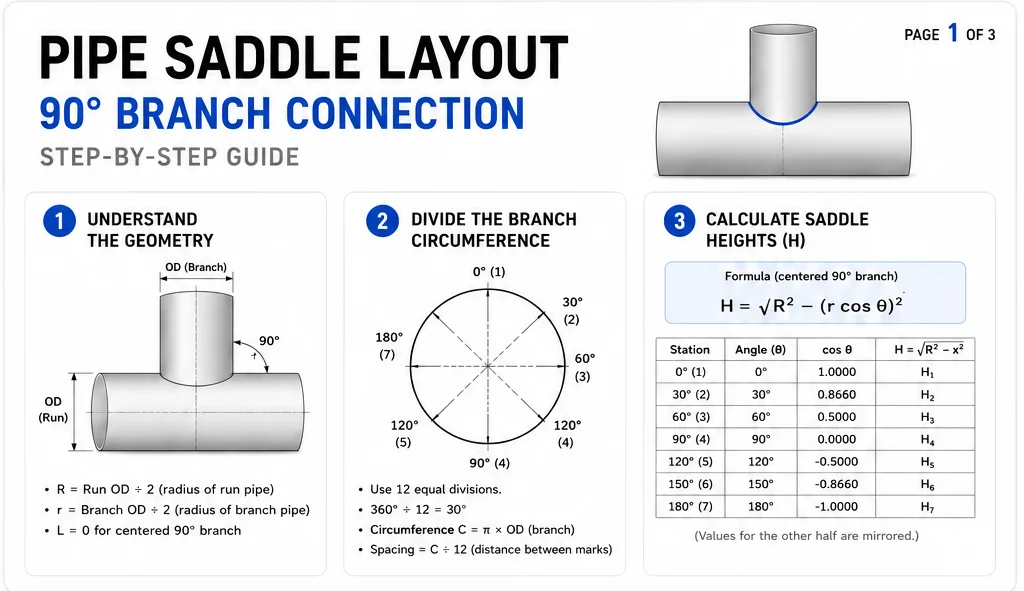
Pipe saddle layout fundamentals: understanding the geometry, dividing the branch circumference, and calculating saddle heights for an accurate 90° branch connection.
Consider the half-circle divided into:
0°
30°
60°
90°
120°
150°
180°
At 0°, cosine is:
cos 0° = 1
At 90°:
cos 90° = 0
At 180°:
cos 180° = −1
Those changing cosine values describe the horizontal position of points around the circular branch.
For example:
x = L + r cos θ
At 0°:
x = L + r
At 90°:
x = L
At 180°:
x = L − r
That changing x-position is then inserted into the run-pipe circle equation:
H = √(R² − x²)
Now you have the corresponding height.
Repeat that calculation at each angular station and you have the mathematical coordinates needed to develop the saddle.
Step 1: Establish Your Branch Circumference
First calculate the circumference of the branch pipe.
C = π × OD
Suppose the branch has an actual OD of 6.625 inches.
Its circumference is approximately:
6.625 × π = 20.81 inches
If you’re using 12 equal divisions:
20.81 ÷ 12 ≈ 1.734 inches
So your stretch-out line would have a station approximately every 1.734 inches.
Those marks correspond to the angular divisions around the branch.
This is how you convert a round pipe into a flat layout.
You’re effectively “unrolling” its circumference.
Step 2: Establish a Reference Line
Never start randomly measuring saddle depths around the pipe.
Establish a reference.
Depending on the layout method, this may be a square-cut end, baseline, centerline or another known plane.
Every calculated ordinate must be measured from the same reference.
This is one of the easiest places to introduce error.
If some dimensions are measured from the end of the pipe and others are measured from a different layout line, the individual calculations can all be correct while the finished saddle is wrong.
Consistency of reference is everything.
Step 3: Mark the 12 Circumference Stations
Using your calculated circumference spacing, mark the stations around the branch.
Label them so you don’t lose track:
0 – 30 – 60 – 90 – 120 – 150 – 180
Then continue around the opposite half.
Another common field method is simply numbering the divisions:
1 through 12
Either works.
The important thing is knowing which physical line around the branch corresponds to which calculated angle.
Extend each station longitudinally along the pipe using a straightedge, wraparound, combination square or another appropriate layout method.
Now you have the grid onto which the saddle measurements will be transferred.
Step 4: Calculate the Saddle Heights
Calculate H for each required angle.
For a 12-division layout, that normally means calculating the unique values from 0° through 180° and mirroring them.
A worksheet is useful here.
Your calculations might conceptually look like:
H₀ = √[R² − (L + cos 0° × r)²]
H₃₀ = √[R² − (L + cos 30° × r)²]
H₆₀ = √[R² − (L + cos 60° × r)²]
H₉₀ = √[R² − (L + cos 90° × r)²]
Continue through 180°.
Don’t round aggressively during intermediate calculations.
Keep several decimal places while calculating and round only when converting the final result into whatever measurement precision is practical for fabrication.
Premature rounding can accumulate error.
Step 5: Convert Heights Into Cutback Measurements
This is an area where people can get confused.
The calculated H values aren’t necessarily the dimensions you directly mark backward from the end of the branch.
That depends on the layout’s datum.
You may need to establish the maximum theoretical height and subtract the individual heights from it to obtain the actual cutback—or “drop”—at each station.
Conceptually:
Cutback = Reference Height − H
The station with the greatest cutback creates the deepest part of the fishmouth.
The stations with smaller cutbacks remain farther forward.
This difference in depth creates the familiar two-horn saddle shape.
Always understand whether your table gives you:
absolute height, or
cutback from a reference plane.
Confusing those two can reverse or distort the entire pattern.
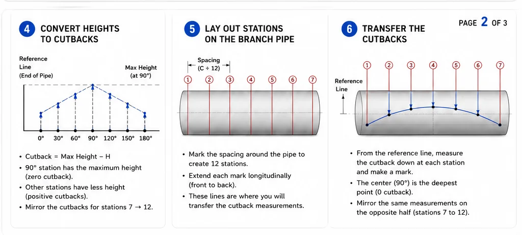
Turning saddle calculations into field layout: establish the stations, calculate the cutbacks, and transfer each measurement to the branch pipe.
Step 6: Transfer the Measurements Onto the Pipe
Now the mathematics becomes fabrication.
At each longitudinal station line, measure the corresponding cutback from your established reference and make a clear mark.
You’ll eventually have a series of dots wrapping around the pipe.
Do not connect them with straight, sharp segments.
The actual intersection is a continuous curve.
Blend the points smoothly.
A flexible strip, contour-friendly straightedge, soapstone and experienced hand can help establish the transition.
Think of your calculated points as checkpoints through which the true curve must pass.
Step 7: Check the Pattern Before Cutting
Before firing up the torch, plasma cutter or grinder, inspect the complete layout.
Confirm that your station spacing is correct.
Confirm symmetry.
Confirm that corresponding points on opposite sides agree.
Confirm your deepest and shallowest portions occur where the geometry says they should.
Check your dimensions again.
This is where the old trade rule matters:
Layout is cheaper than rework.
Five minutes spent checking calculations is nothing compared with replacing a piece of pipe after cutting the saddle backward or from the wrong reference.
Step 8: Cut Outside the Line
For manual fabrication, don’t destroy your layout line immediately.
Leave enough material to finish accurately.
Make the rough cut slightly proud of the final profile, then grind or otherwise finish toward the line as appropriate for the material, procedure and fabrication requirements.
A calculated saddle gets you extremely close.
Final preparation still has to account for the joint configuration required for welding.
The objective isn’t merely getting the branch to “sit” on the run.
The objective is producing the required weld joint geometry.
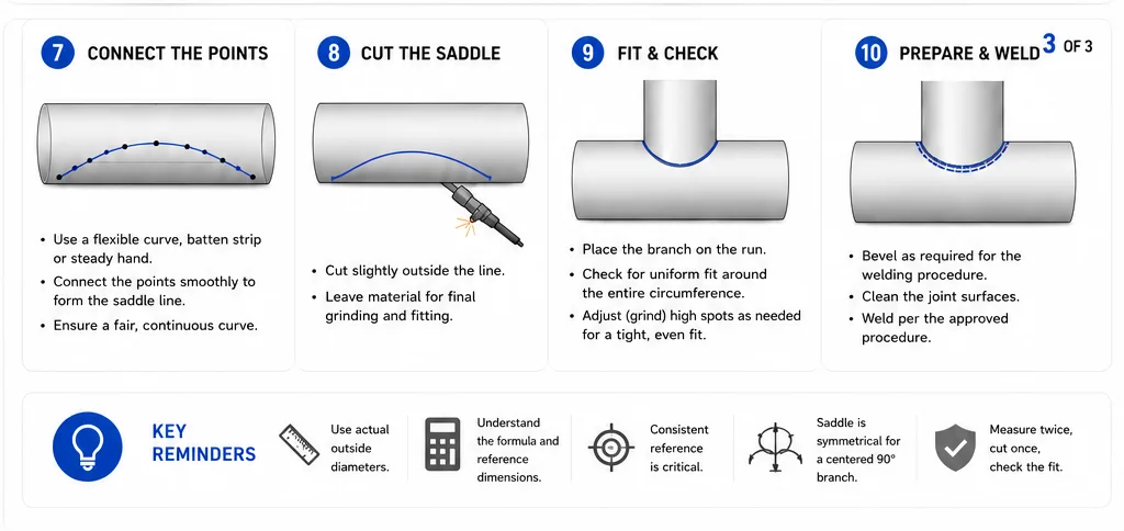
Final pipe saddle fabrication: connect the layout points, cut the profile, check the fit, and prepare the branch connection for welding.
Fit-Up Is the Real Test
After cutting, place the branch against the run pipe and inspect the fit around the entire circumference.
Look for excessive gaps.
Check the branch angle.
Verify centerline orientation.
Check that the branch hasn’t rolled.
Make sure the saddle is actually sitting where intended rather than touching at a few high spots.
If grinding is required, remove material deliberately.
Don’t chase one gap around the pipe until the entire saddle has been destroyed.
High spots should tell you where interference exists.
Remove the high spots gradually, recheck and repeat.
A well-calculated layout should require relatively little correction compared with a saddle developed entirely by trial and error.
What Changes for an Angled Branch?
A 90° branch is only the beginning.
When the branch enters the run at an angle other than 90°, the development becomes an oblique intersection.
Now the saddle becomes asymmetrical.
One side stretches farther than the other, and the simple mirrored relationship of the centered 90° branch no longer applies in the same way.
That requires additional trigonometric relationships to account for the branch angle.
The principle, however, remains the same:
Define the geometry.
Divide the circumference.
Calculate the intersection at each station.
Transfer the ordinates.
Connect the points.
Cut and verify.
Once you understand the geometry rather than memorizing a pattern, more complicated branch developments become much easier to understand.
Why More Divisions Can Improve Accuracy
Suppose you developed the entire saddle using only four points.
You could connect those points, but the resulting profile would be crude.
Now use 8 points.
Better.
Use 12.
Better again.
Use 24 and the calculated development begins approximating the true curve very closely.
This is the same mathematical idea used in many fabrication developments: more points provide a better representation of a curved surface.
But there is a practical balance.
Field fabrication doesn’t necessarily benefit from calculating hundreds of points when cutting and fitting tolerances are much larger than the mathematical difference between them.
The goal is sufficient accuracy—not unnecessary mathematics.
Common Saddle-Layout Mistakes
Several errors cause more trouble than complicated math ever will.
Using nominal pipe size instead of the correct outside diameter is one.
Mixing radius and diameter is another.
A third is entering degrees incorrectly into a calculator. If you’re working with 30°, 60° and 90°, make sure the calculator is in degree mode, not radians.
Other common problems include measuring from inconsistent references, reversing the station sequence, rounding too early, forgetting that the pattern mirrors, incorrectly transferring the circumference spacing and confusing calculated height with actual cutback.
Then there’s the oldest mistake in fabrication:
Doing all the math correctly and cutting on the wrong side of the line.
A Calculator Doesn’t Replace Understanding
Modern pipefitters can use scientific calculators, spreadsheets, CAD programs, layout applications and CNC equipment to generate intersection profiles quickly.
Those tools are valuable.
But knowing the underlying geometry still matters.
If software gives you a strange-looking pattern and you understand how the saddle should behave, you’ll recognize that something is wrong.
If you don’t understand the geometry, a wrong number can look just as convincing as a correct one.
The best pipefitters aren’t opposed to technology.
They understand enough to verify it.
The Field Shortcut: Wraparound Pattern
Once a saddle has been developed accurately, the pattern can also be transferred to suitable pattern material and wrapped around identical branch pipe.
That can save substantial time when fabricating repeated connections of the same dimensions and geometry.
But remember:
A template is only valid for the geometry it was developed for.
Change the branch OD, run OD, intersection angle or relevant offset and the old template may no longer represent the correct intersection.
Never let convenience turn a good pattern into the wrong pattern.
The Bigger Lesson Behind Saddle Development
Pipe saddle layout is a perfect example of why pipefitting is much more than measuring and cutting steel.
You’re taking two three-dimensional cylindrical surfaces and determining the exact curve where they intersect.
Then you’re converting that three-dimensional geometry into a series of measurements that can be physically marked on a piece of pipe.
That’s applied mathematics.
Circle geometry determines the run surface.
Trigonometry determines the location around the branch.
Circumference development converts the round surface into measurable stations.
And fabrication turns those numbers back into a three-dimensional joint.
Once you understand that process, the formulas stop looking like random equations on a piece of paper.
You can see what they’re describing.
From Numbers to Steel
The workflow can be reduced to one sequence:
Measure → calculate → divide → transfer → connect → cut → fit → verify.
But every step depends on the one before it.
Wrong OD?
The calculations are wrong.
Wrong circumference division?
The points are misplaced.
Wrong reference?
The ordinates mean nothing.
Wrong transfer?
The correct math produces the wrong cut.
That’s why good layout work is deliberate.
A skilled pipefitter doesn’t simply know where to put a mark.
They understand why the mark belongs there.
And when you can take nothing more than pipe dimensions, a calculator and layout tools and develop an accurate branch saddle from scratch, you’re no longer guessing at the shape of the steel.
You’re calculating it.


