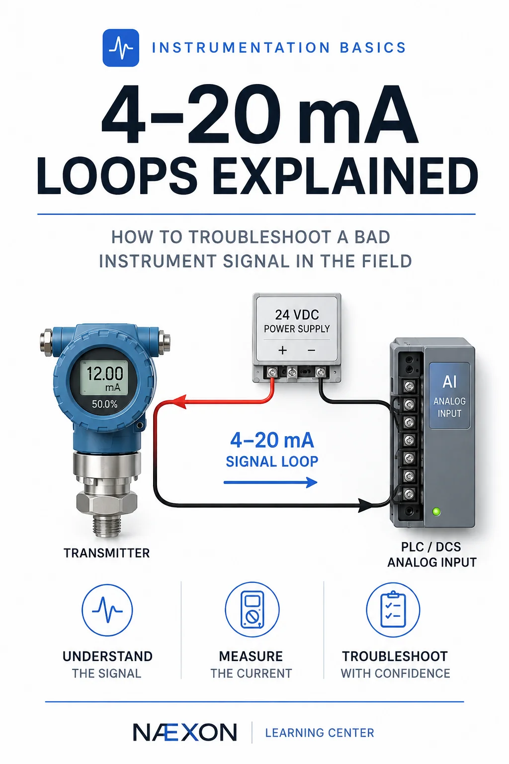
Næxon Learning Center | Instrumentation & Controls Fundamentals
Walk through almost any refinery, chemical plant, power plant, compressor station, or industrial process facility and you will eventually encounter a 4–20 mA signal loop.
Pressure transmitters use them.
Flow transmitters use them.
Level transmitters use them.
Temperature transmitters use them.
Control valves and other field devices may also use analog current signals as part of their control systems.
For an instrumentation technician, electrician, operator, or maintenance worker, understanding the 4–20 mA loop is one of the foundations of industrial troubleshooting.
A control-room screen may show the wrong pressure.
A level transmitter may suddenly indicate zero.
A valve may not respond correctly.
A flow reading may freeze.
The temptation is to immediately blame the instrument.
But the instrument is only one part of the loop.
The problem could be the transmitter, power supply, wiring, termination, analog input, configuration, process connection, or even the process itself.
The technician’s job is to determine where the signal stops making sense.
What Is a 4–20 mA Signal?
A 4–20 mA loop represents a process measurement using electrical current.
The basic relationship is:
4 mA = 0% of calibrated range
8 mA = 25%
12 mA = 50%
16 mA = 75%
20 mA = 100%
Consider a pressure transmitter calibrated:
0–200 PSI
The signal relationship becomes:
4 mA = 0 PSI
8 mA = 50 PSI
12 mA = 100 PSI
16 mA = 150 PSI
20 mA = 200 PSI
This allows the control system to convert an electrical current into a meaningful process value.
The transmitter measures the physical process.
The loop carries that information.
The control system interprets it.
Why Does the Signal Start at 4 mA Instead of 0 mA?
This is one of the most important concepts to understand.
If zero process value were represented by zero current, technicians could have difficulty distinguishing between:
The process is actually at zero
and
The electrical loop is broken.
Using 4 mA as the lower end creates what is commonly called a live zero.
A healthy transmitter measuring the bottom of its calibrated range normally produces approximately 4 mA.
If the circuit is open and current disappears, the reading can fall toward 0 mA.
That immediately gives troubleshooting information.
Zero current and zero process are therefore not necessarily the same thing.
The Basic 4–20 mA Loop
A simple loop may contain:
24 VDC power supply → transmitter → wiring → analog input → return
Current flows through the circuit.
In a two-wire transmitter, the same pair of wires commonly provides operating power and carries the measurement signal.
That simplicity is one reason current loops became so common in industrial instrumentation.
The exact architecture varies between installations, so technicians should always verify the applicable drawings and equipment documentation before testing.
Understanding Loop Current
One important electrical principle makes troubleshooting easier:
In a properly wired series circuit, the same current flows through the entire loop.
If the transmitter is producing 12.00 mA, approximately 12.00 mA should be flowing through the series loop.
That means technicians can often isolate problems by comparing what the field device says it is producing with what the receiving system says it is seeing.
For example:
Transmitter display:
12.02 mA equivalent
Measured loop current:
12.01 mA
DCS indication:
100 PSI
If the transmitter range is 0–200 PSI, those numbers make sense.
But suppose the transmitter produces:
12.00 mA
while the DCS displays:
150 PSI
Now something is wrong downstream of the transmitter signal.
The current may be correct while the control-system scaling is incorrect.
That distinction matters.
Converting Milliamps to Percent
A 4–20 mA signal spans:
20 − 4 = 16 mA
So the percentage of range can be calculated using:
Percent = (Measured mA − 4) ÷ 16 × 100
Suppose you measure:
13.6 mA
Calculate:
13.6 − 4 = 9.6
9.6 ÷ 16 = 0.60
0.60 × 100 = 60%
The transmitter is therefore producing a signal corresponding to:
60% of calibrated span
If the transmitter range is:
0–500 PSI
Then:
500 × 0.60 = 300 PSI
So:
13.6 mA = 300 PSI
for that particular calibration.
This calculation is extremely useful when comparing field measurements against control-room indications.
Converting Process Value to Expected Milliamps
You can also work backward.
Suppose a level transmitter is calibrated:
0–30 ft
The actual level is known to be:
18 ft
Determine percentage:
18 ÷ 30 = 0.60
So the process is at:
60%
Now calculate signal:
16 mA × 0.60 = 9.6 mA
Add the live zero:
9.6 + 4 = 13.6 mA
Therefore, a properly scaled transmitter should produce approximately:
13.6 mA
at 18 feet.
Being able to move between process units, percentage, and milliamps is one of the most useful basic instrumentation skills.
A General 4–20 mA Formula
For a process range with a zero-based lower value:
mA = 4 + 16(Process Value ÷ Full Scale)
For more general ranges where the lower range value is not zero:
mA = 4 + 16 × [(PV − LRV) ÷ (URV − LRV)]
Where:
PV = Process Value
LRV = Lower Range Value
URV = Upper Range Value
This becomes important when dealing with ranges such as:
−50°F to 250°F
or
20 PSI to 120 PSI
rather than simple zero-based ranges.
Understanding this kind of field math works hand in hand with the measurement and calculation principles covered throughout the Næxon Learning Center, including our industrial math and measurement training.
Example: Temperature Transmitter
Suppose a transmitter is ranged:
−50°F to 250°F
Total span:
250 − (−50) = 300°F
Actual temperature:
100°F
Distance above LRV:
100 − (−50) = 150°F
Percentage:
150 ÷ 300 = 50%
Expected signal:
4 + (16 × 0.50)
= 4 + 8
= 12 mA
Even though the process value is 100°F, the transmitter outputs 12 mA because 100°F is exactly halfway through its configured range.
This is why technicians should never assume that a particular process number corresponds directly to a particular current without checking the instrument range.
The Main Parts of a Loop
When troubleshooting, it helps to mentally divide the loop into sections.
A typical measurement loop may include:
1. The process
What is actually happening inside the pipe, vessel, tank, or equipment?
2. The sensing element
How does the instrument physically detect the process?
3. The transmitter
Is the measured variable being converted correctly into the output signal?
4. The power source
Does the loop have the required electrical supply?
5. Field wiring
Are the conductors intact and correctly terminated?
6. Junction boxes and marshalling
Are intermediate connections secure?
7. Analog input
Is the PLC, DCS, or other receiving device actually receiving the current?
8. Scaling and configuration
Is the system converting that current into the correct engineering units?
Thinking this way prevents unnecessary parts swapping.
First Question: Is the Process Reading Actually Wrong?
Before opening junction boxes or replacing transmitters, verify the process condition whenever possible and safe.
Suppose the control room reports:
Tank level = 15%
Before assuming the transmitter failed, ask:
Could the tank actually be at 15%?
Can the reading be compared with another instrument?
Is there a sight glass?
Is there a redundant transmitter?
Has the process recently changed?
Did a valve open or close?
Was equipment started or stopped?
Instrumentation troubleshooting starts with understanding the process.
A perfectly functioning transmitter can report a process condition that operators simply weren’t expecting.
Problem 1: The Signal Is Near 0 mA
A current reading near zero may indicate an open circuit or loss of loop power.
Possible causes include:
- blown fuse
- failed power supply
- broken conductor
- loose terminal
- disconnected transmitter
- open circuit
- wiring damage
- incorrect termination
- device failure
The technician should verify the loop voltage and circuit continuity according to the approved procedure.
Do not immediately replace the transmitter.
If the transmitter has no power, a brand-new transmitter won’t fix the problem.
Problem 2: The Signal Is Stuck Near 4 mA
Suppose the process is clearly changing, but the signal remains approximately:
4.0 mA
That means the loop isn’t necessarily dead.
Current exists.
The question becomes:
Why is the transmitter staying at the bottom of its range?
Possible causes include:
- actual process at or below LRV
- plugged impulse line
- closed root valve
- transmitter configuration problem
- sensing-element problem
- calibration problem
- process connection issue
For pressure and differential-pressure instruments, the mechanical connection to the process is just as important as the electronics.
A perfectly healthy transmitter connected to a blocked impulse line cannot correctly measure the process.
Problem 3: The Signal Is Stuck Near 20 mA
The opposite condition can occur.
The instrument remains near the top of its range even though the process should be lower.
Possible causes include:
- process at or above URV
- incorrect range configuration
- process connection problem
- sensor failure
- transmitter fault
- abnormal process condition
Again, determine whether the signal is wrong before assuming the device is bad.
Problem 4: The Field Reading Is Correct but the DCS Is Wrong
This is one of the most useful troubleshooting scenarios.
Suppose a pressure transmitter is calibrated:
0–100 PSI
The field transmitter indicates:
50 PSI
Measured loop current:
12.00 mA
But the DCS displays:
75 PSI
The transmitter appears to be doing its job.
At 50% of range, 12 mA is exactly what we expect.
Now attention moves downstream.
Possible problems include:
- incorrect DCS scaling
- wrong analog input configuration
- wrong channel assignment
- engineering-unit configuration
- software configuration
- wiring landed on the wrong channel
This is why measuring the actual current can quickly divide a troubleshooting problem in half.
Problem 5: The DCS Is Correct but the Local Display Is Wrong
Now reverse the situation.
Measured current:
12.00 mA
DCS:
50 PSI
Local transmitter display:
65 PSI
If the range is 0–100 PSI, the loop current and DCS agree.
The local indication does not.
That suggests investigation should focus on the transmitter’s local display, configuration, or internal mapping rather than immediately blaming the entire loop.
Problem 6: The Signal Jumps Around
Intermittent problems can be more difficult than complete failures.
The signal might jump:
11.9 mA
12.1 mA
16.8 mA
9.4 mA
12.0 mA
Possible causes include:
- loose terminal
- damaged conductor
- poor connection
- intermittent power
- electrical interference
- grounding problems
- moisture intrusion
- failing transmitter
- unstable process
- process pulsation
Do not overlook the last two.
An unstable signal does not automatically mean electrical noise.
The process itself may actually be unstable.
This is why instrumentation technicians need both electrical knowledge and process awareness.
Checking Loop Voltage
A 24 VDC supply is common in industrial instrumentation, although actual systems vary.
Voltage measurements can help determine whether sufficient loop power is available.
If expected voltage is missing at the transmitter, trace backward toward the source.
If voltage exists at the source but not at the field device, investigate the wiring and intermediate terminations.
The basic troubleshooting principle is:
Find the last point where the circuit behaves correctly.
Then investigate between that point and the first location where it does not.
This same systematic troubleshooting mindset applies throughout industrial maintenance, whether you’re diagnosing instrumentation, electrical equipment, or rotating machinery such as the soft-foot conditions covered in the Næxon Learning Center’s millwright training.
Measuring Current Correctly
Current measurement is different from voltage measurement.
A voltmeter is normally connected across two points.
An ammeter must normally become part of the current path.
That means the circuit may need to be opened and the meter inserted in series, depending on the testing method and equipment being used.
Improper meter placement can interrupt the process signal, create an electrical fault, damage equipment, or affect operating equipment.
Technicians must use the correct meter function, terminals, procedure, PPE, and site requirements.
Some instrumentation tools and test equipment allow loop measurements using methods specifically designed for industrial signal troubleshooting.
Never treat a live process-control circuit like an ordinary bench circuit.
Using a Loop Calibrator
A loop calibrator is one of the most valuable instrumentation troubleshooting tools.
Depending on the model and application, it may be capable of:
- measuring mA
- sourcing mA
- simulating transmitter output
- supplying loop power
- measuring voltage
Suppose the transmitter is suspected of causing an incorrect control-room reading.
A technician may isolate the appropriate portion of the loop and simulate known current values.
For example:
4 mA
Control room should indicate:
0%
Then:
12 mA
Control room should indicate:
50%
Then:
20 mA
Control room should indicate:
100%
If the control system responds correctly to all three simulated values, the receiving side of the loop is probably functioning correctly.
Investigation can then move toward the transmitter and process side.
The 4–12–20 Test
One of the simplest functional checks is testing three points:
4 mA = 0%
12 mA = 50%
20 mA = 100%
This quickly verifies basic scaling.
For more precise calibration work, additional points may be tested according to site procedures and instrument requirements.
A five-point test might include:
0%
25%
50%
75%
100%
and sometimes the same points again while decreasing the signal to evaluate repeatability or hysteresis.
Calibration and troubleshooting are related, but they are not exactly the same task.
Troubleshooting asks:
Where is the problem?
Calibration asks:
Does the instrument accurately represent known input values within the required tolerance?
Don’t Forget Instrument Range
One of the easiest mistakes is troubleshooting the correct current against the wrong configured range.
Suppose the technician believes the transmitter is ranged:
0–100 PSI
But the transmitter is actually configured:
0–150 PSI
At 75 PSI:
For 0–100 PSI:
75% = 16 mA
For 0–150 PSI:
50% = 12 mA
That is a huge difference.
Before diagnosing a scaling problem, verify:
LRV
URV
engineering units
transmitter configuration
DCS configuration
All sides of the loop must agree.
What About Signals Below 4 mA or Above 20 mA?
Modern transmitters may intentionally produce currents outside the normal measurement range to indicate underrange, overrange, or certain fault conditions.
The exact values and behavior depend on the device, configuration, control system, and applicable standards.
Therefore:
3.6 mA does not automatically mean the same thing on every installation.
And:
21+ mA does not automatically identify one specific failure.
Treat abnormal current as diagnostic information.
Then check the instrument configuration and applicable documentation.
Process Problems That Look Like Instrument Problems
Some of the best instrumentation troubleshooting happens without touching a wire.
Consider a differential-pressure flow measurement.
The transmitter appears to be reading low.
Possible electrical problem?
Yes.
But other possibilities include:
- plugged impulse line
- leaking manifold
- incorrect valve position
- process density change
- plugged primary element
- process pressure change
- process actually flowing less
The same principle applies to level, temperature, and pressure measurement.
Instrumentation exists to measure the process.
You cannot properly troubleshoot the instrument without understanding what it is connected to.
For technicians working around piping systems, the broader mechanical knowledge available throughout the Næxon Learning Center’s pipefitting and industrial fundamentals lessons becomes extremely valuable here.
A Practical Troubleshooting Example
An operator reports:
Pressure transmitter PT-101 is reading 25 PSI in the control room, but the process should be around 75 PSI.
Transmitter range:
0–100 PSI
Start systematically.
Step 1 — Verify the process
Compare against another reliable pressure indication if available.
Suppose the mechanical gauge shows:
74 PSI
The DCS indication is probably incorrect.
Step 2 — Calculate expected current
74% of span:
16 × 0.74 = 11.84 mA
Add 4 mA:
Expected ≈ 15.84 mA
Step 3 — Check the transmitter
Suppose the transmitter indicates approximately:
74 PSI
Good.
Step 4 — Measure loop current
Measured:
15.8 mA
That also agrees.
Now you know something important.
The process, transmitter, and loop current agree.
The DCS does not.
The troubleshooting focus should move toward the receiving channel, scaling, configuration, or associated signal path.
Instead of replacing a perfectly good transmitter, you have isolated the problem logically.
A Better Field Troubleshooting Workflow
When a 4–20 mA loop appears faulty, use a consistent sequence.
1. Understand the complaint
What exactly is wrong?
Zero reading?
High reading?
Low reading?
Frozen signal?
Intermittent signal?
Mismatch between field and control room?
2. Verify the process
Determine whether the indicated condition could actually be real.
3. Verify instrument range
Check LRV, URV, and engineering units.
4. Inspect the field device
Look for physical damage, leaks, plugged connections, closed valves, moisture, loose covers, and obvious installation problems.
5. Check loop power
Verify appropriate supply voltage according to the system design.
6. Measure the signal
Determine the actual loop current.
7. Convert current to percentage
Use:
(mA − 4) ÷ 16 × 100
8. Compare the values
Compare:
Actual process
Local transmitter
Measured mA
PLC/DCS indication
9. Divide the loop
Determine where the values stop agreeing.
10. Correct the cause
Repair the actual problem rather than replacing parts unnecessarily.
11. Verify operation
Confirm the field device and control system agree after the correction.
Common 4–20 mA Troubleshooting Mistakes
One of the biggest mistakes is immediately replacing the transmitter.
Transmitters fail, but so do wires, terminations, power supplies, process connections, configurations, and input channels.
Another mistake is ignoring the process.
The instrument may be telling the truth.
Another is forgetting the configured range.
Twelve milliamps always represents approximately 50% of the configured span, but 50% does not mean the same engineering value for every instrument.
Another mistake is measuring current incorrectly.
Current measurement requires understanding how the meter interacts with the circuit.
And another common mistake is changing several things at once.
If you change the transmitter, wiring, configuration, and calibration simultaneously, you may never know what actually caused the problem.
Good troubleshooting isolates variables.
Field Rule: Follow the Signal
When troubleshooting gets confusing, simplify the problem.
Follow the signal from beginning to end:
Process → Sensor → Transmitter → Current Loop → Analog Input → Control System
At each stage ask:
Does the value still make sense here?
If yes, keep moving.
Eventually you reach a point where:
It made sense here.
But:
It doesn’t make sense there.
The fault is usually somewhere between those two points.
That troubleshooting principle applies far beyond instrumentation.
It is one of the core habits of good industrial maintenance.
Knowledge Check
A pressure transmitter is calibrated:
0–400 PSI
The measured loop current is:
10 mA
What pressure should the control system approximately indicate?
First determine signal above live zero:
10 − 4 = 6 mA
Determine percentage:
6 ÷ 16 = 0.375
0.375 × 100 = 37.5%
Now apply that percentage to the process range:
400 × 0.375 = 150 PSI
Answer:
10 mA ≈ 150 PSI
for a transmitter ranged 0–400 PSI.
Practical Exercise
A level transmitter is ranged:
0–24 ft
The control room shows:
18 ft
A technician measures:
12 mA
Do the values agree?
Start with the measured current:
12 − 4 = 8 mA
8 ÷ 16 = 0.50
The signal represents:
50%
Now calculate 50% of the configured level range:
24 × 0.50 = 12 ft
But the control room displays:
18 ft
The values do not agree.
The measured current corresponds to approximately:
12 ft
while the control system displays:
18 ft
That immediately gives the technician a direction.
Before replacing the transmitter, investigate the analog-input scaling, configuration, channel assignment, and signal path between the measurement point and the displayed process value.
The Instrument Technician’s Standard
A good instrumentation technician doesn’t troubleshoot by guessing which component failed.
They troubleshoot by proving what is working.
Understand the process.
Know the instrument range.
Calculate the expected signal.
Measure the actual current.
Compare the field indication with the control system.
Then follow the signal until the numbers stop agreeing.
A 4–20 mA loop may stretch hundreds or even thousands of feet through an industrial facility, but the troubleshooting principle remains simple:
Process → Measure → Compare → Isolate → Correct → Verify
Once you understand that sequence, a mysterious control-room reading becomes a circuit that can be systematically diagnosed.
Continue building those skills throughout the Næxon Learning Center, where instrumentation, electrical, pipefitting, welding, millwright, rigging, and other industrial fundamentals come together to teach not only how industrial systems are built—but how they actually work in the field.


