Learn | Pipefitting • Math & Layout • Intermediate
A pipe penetration may look simple on a drawing, but a hole that is even slightly misplaced can create major problems once installation begins. Incorrect penetration locations can throw off pipe alignment, insulation clearance, sleeves, supports, firestopping, equipment connections, and nearby trades. The goal isn’t simply to make a hole large enough for the pipe. The goal is to establish the correct pipe centerline at the correct location and elevation while providing the required clearance around the entire assembly.
What Is a Pipe Penetration?
A pipe penetration is any location where piping passes through a wall, concrete floor, slab, roof, metal deck, partition, equipment enclosure, or similar structure. Depending on the design, the pipe may pass through an engineered opening or through a sleeve installed in the wall or floor.
The most important reference is normally the pipe centerline. Once the centerline is correctly established, the pipe OD, insulation, sleeve, clearance, and final opening can be laid out around it.
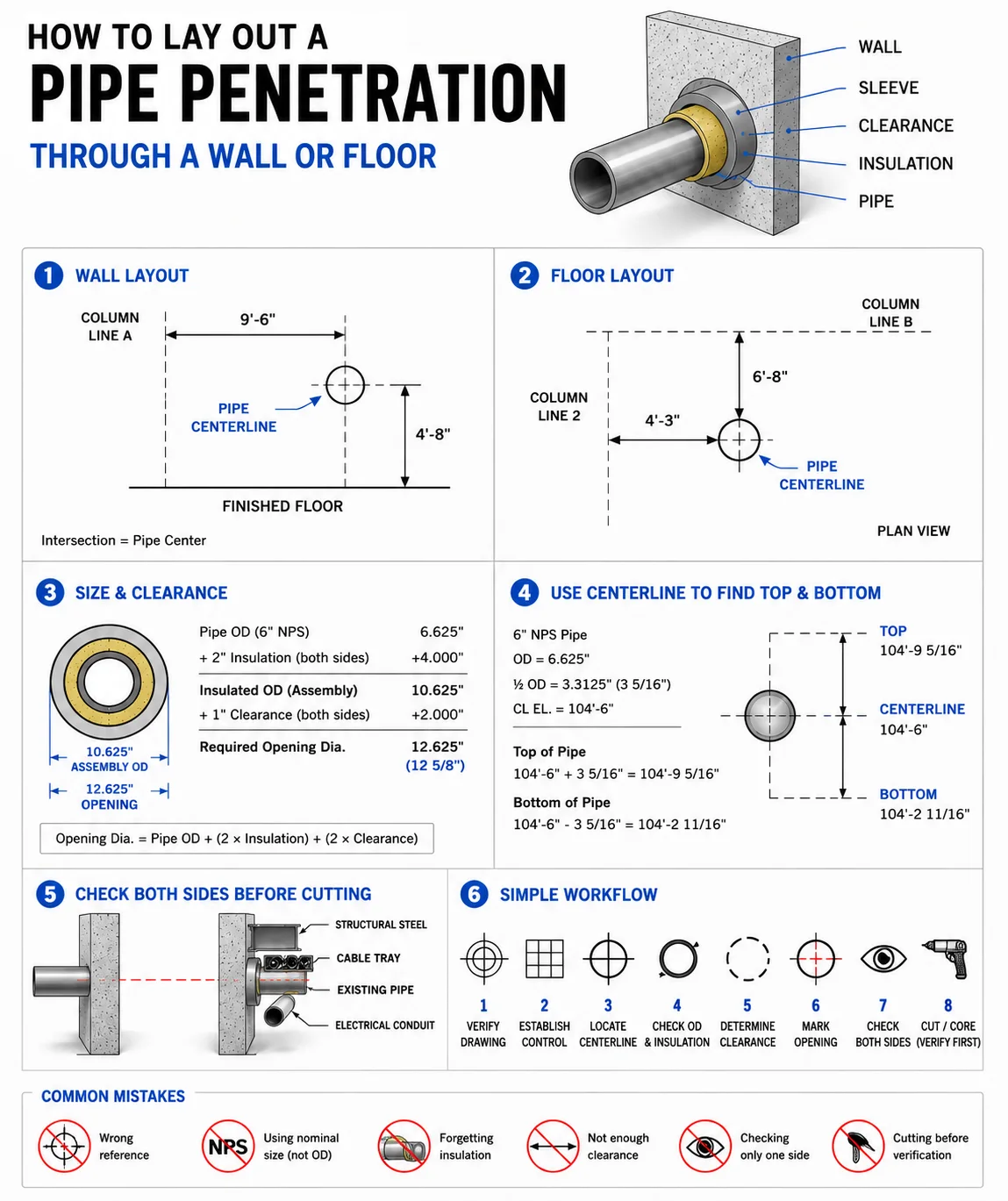
Pipe penetration layout showing how to locate the centerline, account for pipe OD, insulation and clearance, and verify both sides before cutting or coring.
Start With Established References
Never locate an important penetration by measuring from whatever pipe, wall, or piece of steel happens to be nearby. Start from established project control such as column lines, grid lines, benchmarks, finished-floor elevations, or other references identified on the drawings.
For a wall penetration, you normally need two pieces of information: horizontal location and elevation. For a floor penetration, you normally need two horizontal dimensions that establish the pipe’s X-Y position.
Think of the penetration center as a coordinate. Once both dimensions intersect, you have the center of the pipe.
Wall Penetration Layout
Suppose a 6” pipe must penetrate a concrete wall. The drawing gives the pipe centerline as 9’-6” from Column Line A and 4’-8” above finished floor.
First establish Column Line A or the approved horizontal reference. Measure 9’-6” and mark a vertical centerline. Next establish the finished-floor elevation and measure upward 4’-8”. Mark a horizontal centerline.
Where those two lines intersect is the pipe centerline and penetration center.
That center should control the rest of the layout.
Field Rule: Locate the center first. Size the opening second.
Floor Penetration Layout
A vertical pipe passing through a floor is laid out using two horizontal coordinates.
Suppose the drawing shows the pipe centerline 4’-3” east of Column Line 2 and 6’-8” north of Column Line B. Measure 4’-3” from Column Line 2 and establish the first control line. Then measure 6’-8” from Column Line B.
The intersection of those two measurements establishes the pipe center.
Whenever possible, verify the location from another known reference before the opening is made. This helps catch a wrong dimension, wrong grid line, or measurement taken in the wrong direction.
Nominal Pipe Size Is Not Outside Diameter
One of the easiest mistakes in penetration layout is assuming nominal pipe size equals the actual outside diameter.
It doesn’t.
For example, standard 6” NPS pipe has an OD of 6.625”. If you lay out a penetration based on a 6” diameter instead of the actual OD, you’re already starting with the wrong dimension.
Always determine the actual pipe OD before calculating the required opening.
Account for Insulation
The opening may also need to accommodate insulation.
Suppose you have a 6” NPS pipe with a 6.625” OD and the line requires 2” insulation. Because insulation surrounds the pipe, its thickness must be added on both sides.
6.625” + 2” + 2” = 10.625”
The insulated assembly is therefore approximately:
10 5/8” OD
The required penetration may need to be even larger because clearance, sleeves, firestop systems, waterproofing, movement requirements, or other project specifications can affect the final opening size.
Calculate Annular Clearance
Annular clearance is the space between the outside of the pipe or insulated assembly and the inside of the opening or sleeve.
Suppose an insulated pipe assembly is 10” OD and requires 1” clearance around every side. The calculation is:
10” + 1” + 1” = 12”
The theoretical opening diameter is therefore 12”.
The basic formula is:
Opening Diameter = Assembly OD + (2 × Required Radial Clearance)
For insulated pipe:
Assembly OD = Pipe OD + (2 × Insulation Thickness)
Combined:
Opening Diameter = Pipe OD + (2 × Insulation) + (2 × Clearance)
Always verify the final opening or sleeve size against the approved project penetration detail before cutting.
Use Centerline to Find Top and Bottom of Pipe
Once the pipe centerline elevation is known, you can determine the top and bottom of the pipe.
For horizontal pipe:
Top of Pipe = Centerline Elevation + ½ Pipe OD
Bottom of Pipe = Centerline Elevation − ½ Pipe OD
Suppose a 6” NPS pipe has an OD of 6.625”. Half of that diameter is:
6.625 ÷ 2 = 3.3125” = 3 5/16”
If the pipe centerline is EL. 104’-6”, the approximate top of pipe is EL. 104’-9 5/16”, while the bottom of pipe is approximately EL. 104’-2 11/16”.
These dimensions become useful when checking structural steel, concrete, cable tray, ductwork, supports, or another pipe near the penetration.
Transfer the Centerline Through a Wall
Sometimes the same centerline must be established on both sides of a wall. Establish the penetration center on the first side, then transfer the reference using an approved method such as a laser, total station, control lines, known structural references, or a plumb/level reference where appropriate. After transferring the location, verify it independently.
Avoid stacking measurements whenever possible. If you measure from one pipe to another pipe and then use that pipe to locate the penetration, every small error can accumulate. Whenever practical, return to the original project control.
Angled Pipe Penetrations
A pipe passing straight through a wall at 90° to the wall surface creates a relatively straightforward penetration. A pipe passing through the wall at an angle is different because the pipe occupies a larger apparent opening in the direction of travel.
This becomes increasingly important with large-diameter pipe, thick walls, insulated piping, sleeves, and steep penetration angles. Do not automatically assume that the circular opening used for a perpendicular penetration will work for an angled pipe. Check the actual pipe path and approved penetration detail.
Sleeve Layout
If the penetration requires a sleeve, establish the sleeve centerline from the pipe centerline. Then verify the sleeve ID and OD, pipe OD, insulation thickness, annular clearance, wall or slab thickness, required sleeve projection, firestop requirements, and waterproofing requirements.
A sleeve can be perfectly centered and still be unusable if its inside diameter is too small for the completed pipe assembly.
Check Both Sides Before Cutting
A penetration location that looks completely clear from one side of a wall may have structural steel, cable tray, electrical equipment, existing piping, ductwork, equipment, embedded utilities, or another trade’s installation on the opposite side.
Before drilling, coring, or cutting, verify the complete penetration path using the project’s approved procedures. Never assume that because one side is clear, the opening is safe to make.
Be Especially Careful With Structural Concrete
Concrete can contain reinforcing steel, post-tensioning systems, electrical conduit, embedded piping, structural elements, and other systems that may not be visible from the surface.
The piping drawing tells you where the pipe needs to go. It does not automatically authorize cutting through structural material. Coring or drilling should only proceed under the project’s approved procedures and authorization.
Field Layout Workflow
Start by verifying the latest drawing revision and confirming the pipe size, service, centerline location, elevation, insulation, and penetration detail. Establish the correct project control, then locate the pipe centerline. For a wall, establish horizontal position and elevation; for a floor, establish both horizontal coordinates.
Next, verify the actual pipe OD and account for insulation and required clearance. Determine the required sleeve or opening from the approved detail, clearly mark the penetration center, and check the opposite side and complete path. Finally, independently verify the dimensions before drilling, coring, or cutting.
The sequence is simple:
CONTROL → CENTERLINE → PIPE OD → INSULATION → CLEARANCE → OPENING → VERIFY → CUT
Common Mistakes
A common mistake is measuring from the wrong reference instead of using the project’s established grid or benchmark. Another is using nominal pipe size instead of actual OD. Pipefitters also get into trouble by forgetting insulation, misunderstanding radial clearance, or measuring from another pipe and compounding an existing layout error.
Another major mistake is checking only one side of the penetration. The entire path matters. Finally, avoid cutting simply because the layout looks right. A wrong pipe cut can often be repaired relatively easily; a misplaced core hole through a finished concrete wall can become a much larger problem.
Field Rule
Locate the center first. Size the opening second. Cut last.
Before making any penetration, answer three questions:
WHERE does the pipe centerline belong?
HOW LARGE does the approved opening need to be?
IS the complete penetration path cleared and authorized?
If those three questions have been answered correctly, the penetration has a much better chance of landing exactly where the piping system needs it.
Knowledge Check
1. What normally establishes a wall penetration?
Horizontal location and elevation.
2. What normally establishes a floor penetration?
Two horizontal coordinates from established references.
3. Is nominal pipe size the same as actual pipe OD?
No.
4. Why is insulation thickness added twice?
Because insulation extends outward from both sides of the pipe.
5. An 8” OD assembly requires 1” clearance around every side. What theoretical opening diameter is required?
8” + 1” + 1” = 10”
6. What should normally be established first: the edge of the opening or the pipe centerline?
The pipe centerline.
Practical Exercise
An 8” NPS pipe with an actual OD of 8.625” penetrates a wall. The pipe requires 2” insulation and the approved detail requires 1” radial clearance.
First determine the insulated assembly:
8.625” + 2” + 2” = 12.625”
Then add the clearance:
12.625” + 1” + 1” = 14.625”
The theoretical diameter required around the insulated assembly is therefore:
14 5/8”
Now establish the penetration center from the project’s horizontal and elevation controls. Before making the opening, verify the sleeve or penetration size against the approved detail and confirm that the complete path through the wall is cleared.
A good penetration layout isn’t judged simply by whether the pipe fits through the hole. It’s judged by whether the pipe lands exactly where the system was designed to run.


