Learning Center | Electricians | Fundamentals
Walk through almost any refinery, power plant, petrochemical facility, LNG terminal, or large industrial site and you will eventually encounter equipment operating on 480-volt three-phase power. Pumps, compressors, cooling-tower fans, conveyors, large HVAC equipment, and countless electric motors depend on it.
For electricians and other industrial workers, understanding 480V starts with one important idea: 480V three-phase is not simply “a stronger version” of household electricity. It is a power-distribution system designed to efficiently operate substantial industrial loads.
This lesson explains what 480V three-phase means, how the three phases work together, why industrial facilities use it, and how motors, MCCs, starters, overloads, breakers, and VFDs fit into the system.
1. What Does 480V Three-Phase Mean?
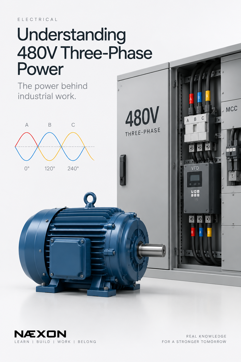
A three-phase system uses three alternating electrical waveforms—commonly identified as:
Phase A — Phase B — Phase C
The phases are separated electrically by 120 degrees.
In a typical 480V system, the nominal voltage measured phase-to-phase is approximately:
A → B = 480V
B → C = 480V
C → A = 480V
The exact measured voltage can vary depending on the electrical system and operating conditions.
This differs from single-phase power because three-phase power delivers energy through three coordinated phases rather than one alternating waveform.
2. Why Do Industrial Plants Use Three-Phase Power?
Industrial facilities need to operate large electrical loads efficiently.
A refinery may have hundreds or thousands of electric motors driving pumps, fans, compressors, conveyors, cooling systems, and process equipment.
Three-phase power is particularly useful for motors because it naturally produces a rotating magnetic field inside a three-phase AC motor.
That rotating field is one of the reasons three-phase induction motors are so common throughout heavy industry.
3. Understanding the 120° Separation
Imagine three sine waves.
They have the same frequency but do not reach their peaks simultaneously.
Instead, each phase is shifted approximately 120 electrical degrees from the next.
Conceptually:
A → 0°
B → 120°
C → 240°
Together, the three phases provide a more continuous transfer of power than a comparable single-phase arrangement.
For an industrial worker, the important concept isn’t memorizing the waveform. It is understanding that A, B, and C are coordinated phases of the same electrical system.
4. Where Does the 480V Come From?
Industrial facilities receive electrical power through transformers and distribution equipment designed for the site’s electrical system.
A common arrangement is a 480Y/277V grounded wye system.
In that system:
Phase-to-phase ≈ 480V
Phase-to-neutral ≈ 277V
The relationship comes from three-phase electrical geometry:
480 ÷ √3 ≈ 277V
This is why workers may hear both 480V and 277V discussed around the same distribution system.
However, not every 480V system has the same configuration. Delta systems and other arrangements also exist, so workers must identify the actual system rather than assuming its configuration.
5. What Equipment Uses 480V?
One of the most common applications is the three-phase electric motor.
These motors may drive centrifugal pumps, cooling-tower fans, compressors, air handlers, conveyors, hydraulic systems, and other rotating equipment.
Large industrial facilities often have enormous numbers of motors distributed throughout the plant.
That creates another challenge:
How do you control and protect all those motors?
That is where the Motor Control Center becomes important.
6. What Is an MCC?
An MCC — Motor Control Center — is an assembly containing equipment used to control and protect motors and other electrical loads.
An MCC can contain multiple compartments commonly called buckets.
Depending on the installation, a bucket may contain components such as a circuit breaker or disconnect, contactor, motor starter, overload protection, control transformer, control devices, and communication equipment.
Instead of installing separate control equipment throughout the facility, MCCs allow many motor circuits to be organized into centralized assemblies.
7. What Does a Motor Starter Do?
A motor starter allows a motor circuit to be controlled while also providing the required protective functions as designed.
A basic magnetic starter commonly includes a contactor and overload protection.
The contactor electrically opens and closes the motor power circuit when commanded by the control system.
For example:
START command → contactor energizes → motor receives three-phase power
STOP command → contactor de-energizes → motor power circuit opens
The actual control scheme may be much more complex in a refinery or power plant because motors can be tied into process-control systems, interlocks, emergency shutdown systems, and equipment permissives.
8. What Is Overload Protection?
A motor can draw excessive current because of mechanical or electrical problems.
Examples include an overloaded driven machine, a stalled rotor, phase problems, excessive mechanical resistance, or other abnormal operating conditions.
Motor overload protection is intended to protect the motor from damaging overload conditions according to its design and settings.
It is important to distinguish this from other protective devices.
A circuit breaker, fuse, overload relay, protective relay, and motor controller may perform different functions within the electrical protection scheme.
They should not all be thought of as doing the same job.
9. What Is a VFD?
Many industrial motors are connected to Variable Frequency Drives, commonly called VFDs.
Instead of simply operating a motor at essentially one fixed speed, a VFD controls motor operation by changing the electrical frequency and voltage supplied to the motor.
Consider a process pump.
The process may not always require maximum flow. Instead of continuously running the motor at full speed and controlling flow only mechanically, a properly designed system may use a VFD to change motor speed based on process demand.
VFDs are common on pumps, fans, cooling towers, conveyors, compressors, and many other industrial applications.
10. Why Phase Rotation Matters
Three-phase motors have another important characteristic.
Changing the phase sequence can change the motor’s direction of rotation.
For example, a motor connected with one phase sequence may rotate one direction. Interchanging two phases changes the phase sequence and can reverse rotation.
This matters tremendously when commissioning equipment.
A pump, fan, compressor, or other rotating machine turning backward can create equipment or process problems.
Motor rotation must therefore be verified using the site’s approved commissioning and electrical procedures.
11. What Is Phase Loss?
A three-phase motor is designed to operate with all three phases available under its intended conditions.
If one phase is lost, the condition is commonly called single-phasing.
A motor subjected to phase loss can experience abnormal current and heating conditions and may be damaged if the protection system does not respond appropriately.
Possible causes can include blown fuses, damaged conductors, loose connections, failed contacts, or upstream electrical problems.
This is one reason electricians troubleshooting motors evaluate the entire three-phase supply rather than looking at only one conductor.
12. The Basic Power Path
A simplified industrial motor circuit might look like:
Utility / Generator
↓
Transformer
↓
Switchgear
↓
MCC
↓
Breaker / Starter / VFD
↓
Motor
↓
Pump, Fan, Compressor or Other Equipment
Actual industrial distribution systems can be considerably more complex, but understanding this basic path gives apprentices a foundation for reading one-line diagrams and troubleshooting electrical systems later.
13. Electricity and the Mechanical Crafts Connect
Electrical problems don’t always originate inside electrical equipment.
Suppose a 480V motor driving a pump begins drawing excessive current.
The problem could involve the electrical supply or motor—but it could also involve the driven equipment.
A failing bearing, binding pump, damaged coupling, misalignment, process condition, or another mechanical problem could increase the load on the motor.
This is why industrial troubleshooting frequently crosses craft boundaries.
A millwright may discover the mechanical problem.
An electrician may see its electrical effect.
An operator may notice the process change.
Understanding how those systems interact makes every craft more effective.
Common Mistakes
One mistake is assuming every conductor associated with a 480V system has exactly the same voltage relationship to ground or neutral. System configuration matters.
Another is assuming that because a motor isn’t turning, the motor itself must be defective. The issue could be upstream power, controls, protection, interlocks, the driven equipment, or another part of the system.
Workers should also never assume equipment is electrically safe simply because it is stopped. Electrical isolation and verification must follow the facility’s approved energy-control and electrical-safety procedures.
Field Rule
Never identify an electrical system by appearance alone.
Labels, drawings, equipment information, approved test procedures, and the facility’s electrical documentation are there for a reason.
480V industrial electrical systems can present severe shock, arc-flash, and arc-blast hazards. Testing, troubleshooting, opening energized equipment, and electrical work should only be performed by personnel authorized and qualified for that work under the applicable facility procedures.
Knowledge Check
1. How many phases are used in three-phase power?
Three: commonly identified as A, B, and C.
2. How far apart are the three electrical phases?
Approximately 120 electrical degrees.
3. On a common 480Y/277V system, what is the approximate phase-to-neutral voltage?
277 volts.
4. What does MCC stand for?
Motor Control Center.
5. What does a VFD control to regulate AC motor operation?
Primarily the frequency and voltage supplied to the motor.
6. Why does phase sequence matter?
Because changing the phase sequence can reverse the direction of rotation of a three-phase motor.
Practical Exercise
Imagine a refinery centrifugal pump driven by a 480V three-phase motor.
The operator starts the pump after maintenance. The motor is energized, but the equipment is not behaving as expected.
Instead of immediately concluding “bad motor,” think through the system:
Power supply → protection → controls → motor → coupling → pump → process
The electrical and mechanical systems are connected. Good industrial troubleshooting works through the system logically instead of replacing components based on assumptions.
Continue Learning
Understanding 480V three-phase power provides the foundation for more advanced Næxon Learning Center lessons covering Motor Control Centers, industrial motors, VFDs, electrical one-line diagrams, transformers, contactors, overloads, instrumentation, control circuits, and electrical troubleshooting.
It also connects directly to the previous millwright lesson on Pump and Motor Alignment, showing how multiple crafts interact around the same piece of rotating equipment.