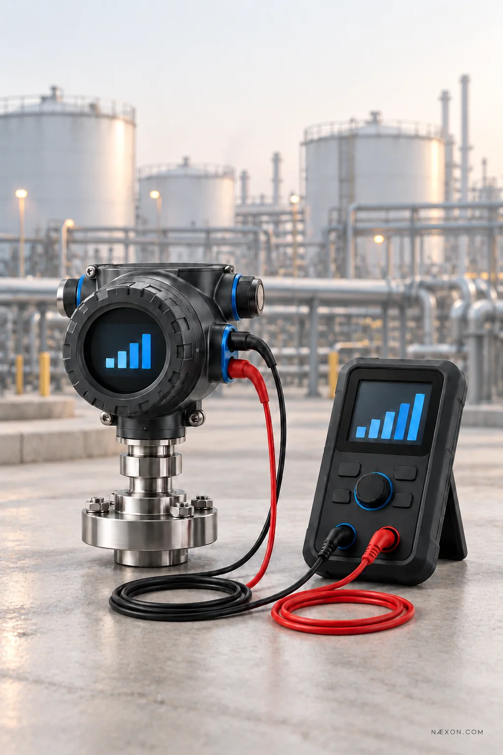
The pressure transmitter shows 50 psi locally. The control room shows 38 psi. Which one is wrong?
Before replacing the transmitter or changing a DCS setting, an instrumentation technician needs to separate three things: the process value measured by the transmitter, the current it sends, and the value the control system displays. A correct local display does not, by itself, prove that the analog output or the rest of the loop is correct.
Confirm the expected signal
Start with the transmitter’s configured range and the control system’s configured range. On a linear 0–100 psi transmitter, 4 mA represents 0 psi, 12 mA represents 50 psi, and 20 mA represents 100 psi. If the transmitter is configured for one range and the DCS scales the input using another, both devices can be functioning while their displayed values disagree.
Confirm the tag, engineering units, lower and upper range values, and any special signal processing. Do not assume every 4–20 mA signal uses simple linear scaling; some applications apply additional calculations in the transmitter or control system.
Check what the transmitter is actually sending
Read the transmitter’s process value, output percentage, and commanded analog output if those diagnostics are available. Then verify the actual loop current with suitable test equipment and the approved procedure. This distinction matters: the transmitter might calculate the right process value but fail to produce the expected current.
For example, if a linear 0–100 psi transmitter displays 50 psi, the expected normal output is 12 mA. If the measured current differs, investigate the transmitter’s output configuration, diagnostics, power, and loop conditions before blaming the DCS display.
Compare the current at the receiving end
If the correct current is leaving the field device, follow the loop toward the control system. Check the documented wiring path, junction boxes, marshalling terminals, isolators, barriers, and analog input channel. Verify that the signal reaches the intended channel and that the input is configured for the circuit actually installed.
Intermittent readings deserve attention to connections, moisture, damaged cable, and available loop power. A transmitter can have trouble maintaining its intended output when the supply and total loop resistance do not meet its requirements.
Test the input and the displayed value
With operations’ authorization and the appropriate loop procedure, a technician can apply a known test signal at a defined point and compare it with the control system’s raw input and displayed engineering value. A 4, 12, and 20 mA check can reveal whether the receiving channel and scaling follow the expected range.
If the raw input is correct but the displayed value is wrong, look at scaling, units, tag assignment, and calculations in the control system. If the raw input is wrong, investigate the input channel, wiring, and devices between the test point and the controller.
A live process signal may feed an alarm, interlock, or control action. Coordinate any disconnection or simulated signal with operations and follow the site’s procedure for protecting the process.
Document the fault before adjusting anything
Record the transmitter range, local process value, commanded output, measured current, receiving-channel value, and control-room display at the same point in time. Note exactly where each measurement was taken. That record shows where the disagreement begins.
Avoid trimming the transmitter or changing DCS scaling just to make two numbers match. First prove which part of the measurement chain is incorrect; then make the approved correction and perform an end-to-end check.
The takeaway: when a transmitter and control room disagree, follow the signal in order: process value → analog output → loop wiring → input channel → displayed value. The first point where the numbers stop agreeing tells you where to focus.
Editorial fact-check, separate from the article: Instrument and calibration guidance supports checking actual loop current, applying known signals to the receiving system, and matching transmitter and control-system configuration.


