The Fluid Catalytic Cracking unit—commonly called the FCC or FCCU—is one of the most important conversion units in many refineries. Instead of simply separating hydrocarbons by boiling point, the FCC actually changes their molecular structure.
Its job is to take heavier hydrocarbon molecules and crack them into smaller, more valuable products.
At the center of the FCC are two major pieces of equipment that operate together continuously: the reactor and regenerator.
The reactor is where hydrocarbons contact extremely hot, finely powdered catalyst and crack into lighter molecules. The regenerator is where coke deposited on that catalyst is burned away so the catalyst can be reheated and returned to the reactor.
The continuous circulation can be simplified as:
Hot Catalyst → Reactor → Coke-Containing Catalyst → Regenerator → Clean Hot Catalyst → Reactor
Understanding this loop is one of the keys to understanding how an FCC works.
What Is Fluid Catalytic Cracking?
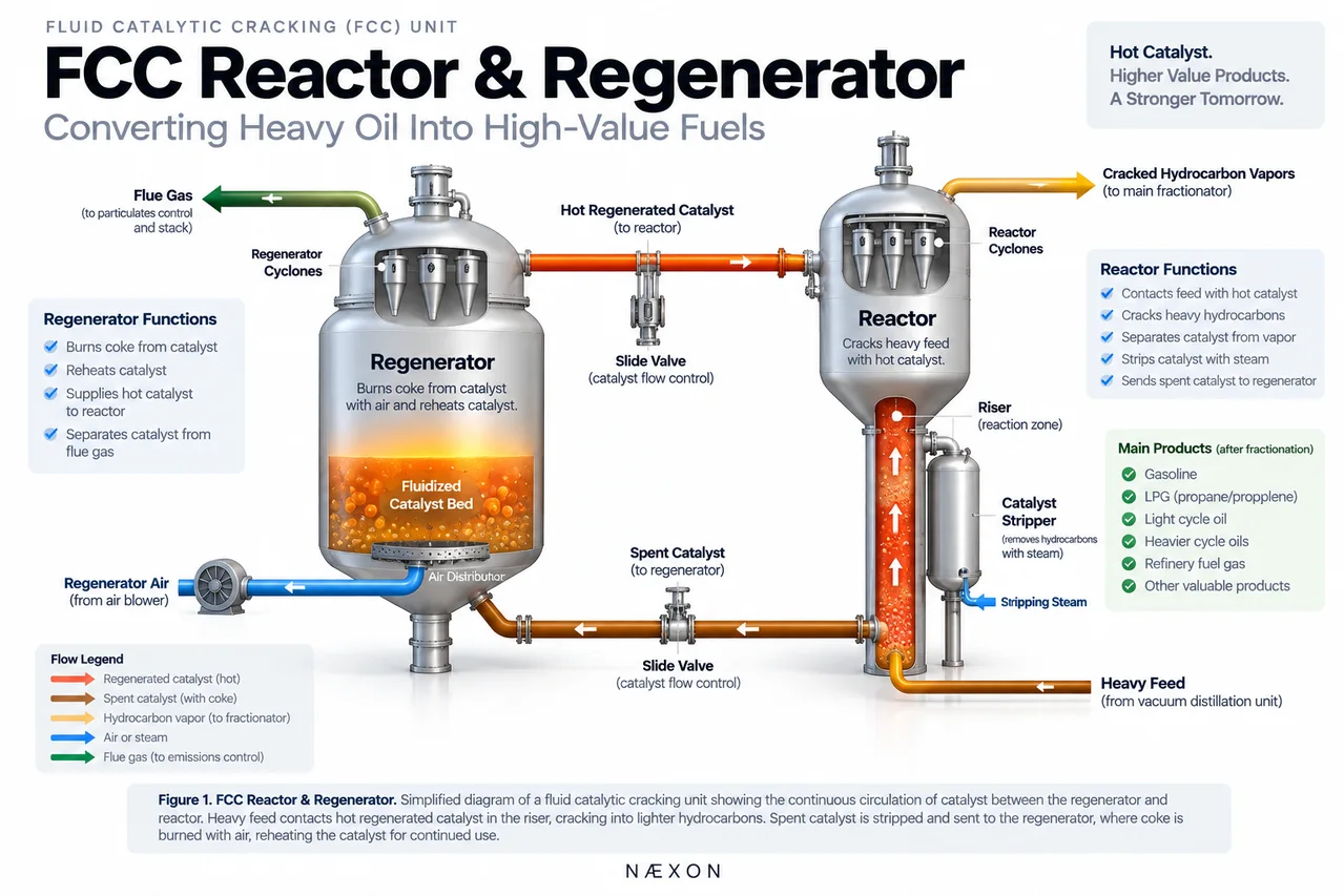
Figure 1. FCC Reactor & Regenerator. Simplified fluid catalytic cracking diagram showing how heavy feed contacts hot regenerated catalyst in the riser, cracked hydrocarbon vapors leave toward fractionation, and spent catalyst returns to the regenerator where coke is burned off before the reheated catalyst circulates back to the reactor.
Fluid catalytic cracking is a refinery conversion process that uses heat and catalyst to break large hydrocarbon molecules into smaller molecules.
The feed normally comes from heavier refinery streams that would otherwise have considerably less value than gasoline and other lighter products.
The basic process is:
Heavy Feed → Hot Catalyst → Cracking Reaction → Lighter Hydrocarbons
The resulting hydrocarbon vapor contains many different molecules that are later separated into useful refinery streams.
Unlike the crude and vacuum distillation units, which primarily separate hydrocarbons according to boiling range, the FCC changes the molecules themselves.
Why Refineries Use the FCC
Crude distillation separates crude oil into fractions according to boiling range, but separation alone does not necessarily produce the product mix the refinery wants.
A refinery may have more heavy material than the market requires while demand is much greater for lighter products.
The FCC helps change that balance.
Depending on the refinery and operating strategy, FCC products can contribute to streams associated with:
- Gasoline production.
- LPG.
- Propylene and other light olefins.
- Light cycle oil.
- Heavier cycle oils.
- Refinery fuel gas.
Instead of merely separating molecules, the FCC converts them.
The Reactor and Regenerator Work as One System
The FCC reactor and regenerator cannot really be understood independently.
The reactor needs hot, active catalyst.
The regenerator receives catalyst from the reactor, removes coke through combustion, reheats the catalyst, and returns it.
The continuous loop is:
Regenerator → Hot Regenerated Catalyst → Reactor → Spent Catalyst → Regenerator
Catalyst continuously circulates between these sections while the unit operates.
This is one of the defining characteristics of fluid catalytic cracking.
What Is FCC Catalyst?
FCC catalyst is a very fine solid material engineered to promote cracking reactions.
Rather than using large fixed catalyst pellets, the FCC uses extremely small catalyst particles.
When these particles are suspended in moving gas or vapor, they can behave somewhat like a fluid.
This allows catalyst to move continuously through the FCC.
The catalyst provides active surfaces where large hydrocarbon molecules can crack into smaller molecules.
Because enormous quantities of catalyst circulate continuously, catalyst movement is central to FCC operation.
Feed Enters the Reactor System
Heavy hydrocarbon feed enters the reactor section and contacts extremely hot regenerated catalyst arriving from the regenerator.
The hot catalyst supplies much of the thermal energy required to vaporize the feed and drive the cracking reactions.
The sequence is:
Heavy Feed + Hot Regenerated Catalyst → Rapid Vaporization → Catalytic Cracking
The reaction occurs extremely quickly.
Important FCC cracking reactions can take place within only a few seconds.
The FCC Riser
In many FCC designs, much of the actual cracking occurs inside a vertical pipe called the riser.
Feed is injected near the lower portion of the riser and immediately contacts hot regenerated catalyst.
The hydrocarbon vapor and catalyst then travel upward together.
During this short journey:
Feed Vaporizes → Molecules Contact Catalyst → Large Molecules Crack → Lighter Molecules Form
The riser is therefore much more than a transfer pipe.
It is one of the primary reaction zones of the FCC.
Why Contact Time Matters
Cracking must be carefully controlled.
If hydrocarbons remain exposed to hot catalyst longer than intended, secondary reactions can continue changing the products.
FCC operation therefore depends heavily on controlling conditions such as:
- Reactor temperature.
- Catalyst circulation.
- Feed rate.
- Catalyst-to-oil ratio.
- Contact time.
- Feed characteristics.
Changes in these conditions can influence the product distribution of the entire unit.
Reactor Separation
At the top of the riser, cracked hydrocarbon vapors must be separated rapidly from the catalyst.
If catalyst remains mixed with hydrocarbon vapor, cracking can continue longer than desired.
Cyclone separators are commonly used inside the reactor vessel.
The basic separation is:
Hydrocarbon Vapor + Catalyst → Cyclones → Catalyst Separates → Hydrocarbon Vapor Continues
The hydrocarbon vapor leaves toward downstream fractionation.
The catalyst moves toward the stripping section.
FCC Cyclones
Cyclones use centrifugal action to separate catalyst particles from gas.
The gas-and-catalyst mixture enters the cyclone and begins swirling.
The heavier catalyst particles move toward the cyclone wall and fall downward while the gas exits through the upper portion.
FCC cyclones operate under severe conditions.
They encounter:
- High temperatures.
- Catalyst erosion.
- Continuous solids loading.
- Thermal cycling.
- High gas velocities.
Cyclone condition is therefore an important concern during FCC inspections and turnarounds.
The Catalyst Stripper
Catalyst leaving the reactor still carries hydrocarbon vapor.
Before the catalyst enters the regenerator, as much recoverable hydrocarbon as practical should be removed.
The catalyst therefore passes through a stripping section where steam contacts the catalyst.
The simplified process is:
Spent Catalyst + Steam → Hydrocarbon Vapor Removed → Stripped Catalyst
Recovered hydrocarbons return toward the reactor vapor system.
The stripped catalyst continues toward the regenerator.
Why Catalyst Becomes Spent
During cracking, carbon-rich deposits called coke accumulate on the catalyst.
Coke covers active catalyst surfaces and reduces catalyst effectiveness.
The catalyst leaving the reactor is therefore commonly called spent catalyst.
But the catalyst is not simply discarded.
It is regenerated and reused.
The Regenerator
The regenerator restores catalyst activity by burning coke from the catalyst.
Air is introduced into the regenerator.
The coke reacts with oxygen and burns.
The simplified process is:
Spent Catalyst + Air → Coke Burns → Regenerated Catalyst + Flue Gas + Heat
This accomplishes two extremely important jobs.
It removes coke from the catalyst.
It also heats the catalyst.
That hot regenerated catalyst can then return to the reactor and supply thermal energy for another cracking cycle.
The FCC Heat Balance
One of the most important concepts in FCC operation is the relationship between reactor and regenerator heat.
Cracking requires heat.
Coke combustion produces heat.
The unit transfers that energy using the circulating catalyst.
The basic energy cycle is:
Coke Burns in Regenerator → Catalyst Gets Hot → Hot Catalyst Enters Reactor → Catalyst Supplies Heat → Catalyst Returns to Regenerator
The catalyst therefore performs two major functions.
It promotes cracking reactions and transports thermal energy between the reactor and regenerator.
Regenerator Air System
The regenerator requires a large controlled supply of air to burn coke.
Air enters through an engineered distribution system near the lower portion of the vessel.
Proper air distribution is important because combustion must occur throughout the catalyst bed.
Poor air distribution can contribute to uneven combustion and abnormal temperature conditions.
The air system can include:
- Air blower.
- Large air piping.
- Distribution grid.
- Control valves.
- Instrumentation.
Loss of regenerator air can become a major FCC operating event.
Regenerator Cyclones
Combustion gases leaving the catalyst bed can carry catalyst particles upward.
Cyclones inside the regenerator separate much of this catalyst from the flue gas.
The process is:
Flue Gas + Catalyst → Regenerator Cyclones → Catalyst Returns → Flue Gas Leaves
This helps retain catalyst inside the system and reduces catalyst carried downstream with the flue gas.
Flue Gas
After coke combustion and catalyst separation, hot flue gas leaves the regenerator.
Depending on refinery configuration, the flue gas may pass through additional equipment associated with energy recovery, particulate removal, emissions control, or other treatment.
For refinery workers, the important point is that the regenerator is both a catalyst-regeneration vessel and a major combustion system.
Catalyst Circulation
Catalyst circulation between the reactor and regenerator must be carefully controlled.
The simplified catalyst loop is:
Regenerator → Regenerated Catalyst → Riser → Reactor → Stripper → Spent Catalyst → Regenerator
Specialized valves regulate catalyst movement between the vessels.
Because catalyst behaves like a fluidized solid, controlling its movement is fundamentally different from controlling ordinary liquid flow through refinery piping.
Slide Valves
Large specialized valves are commonly used to control catalyst circulation.
These are often called slide valves.
Their position influences the amount of catalyst moving through the system.
Slide valves operate in extremely severe service involving:
- Hot catalyst.
- Abrasive solids.
- High temperatures.
- Differential pressure.
- Continuous operation.
They are critical pieces of FCC equipment.
Fluidization
Fluidization is one of the fundamental principles behind FCC operation.
When gas flows upward through fine catalyst particles at sufficient velocity, the particles become suspended and begin behaving somewhat like a boiling liquid.
This allows catalyst to:
- Flow through equipment.
- Mix with hydrocarbons.
- Circulate between vessels.
- Transfer heat.
- Be continuously regenerated.
Without fluidization, the modern FCC process could not operate in the same manner.
Reactor and Regenerator Pressure
The reactor and regenerator operate as interconnected pressure systems.
The pressure relationship between the two vessels is important because catalyst must circulate in the intended direction while unwanted gas movement between the systems must be controlled.
Operators therefore monitor differential pressure carefully.
Incorrect pressure balance can interfere with catalyst circulation and overall FCC stability.
Why the FCC Is So Hot
FCC equipment operates at high temperatures because both catalytic cracking and catalyst regeneration depend on substantial thermal energy.
These conditions create demanding service for:
- Vessel shells.
- Refractory.
- Piping.
- Expansion joints.
- Valves.
- Internals.
- Pipe supports.
- Instrumentation.
- Structural steel.
Workers must also remember that large refractory-lined equipment can retain heat for a considerable period after shutdown.
Refractory
Many FCC components contain refractory lining.
Refractory helps protect metal from extreme temperatures and, in certain applications, abrasive catalyst erosion.
Refractory-lined areas can include:
- Reactor sections.
- Regenerator sections.
- Risers.
- Transfer lines.
- Cyclones.
- High-temperature piping.
Refractory condition is critical.
If refractory is damaged, the underlying metal may become exposed to temperatures or erosion conditions it was not designed to experience directly.
Catalyst Erosion
FCC catalyst is highly abrasive.
Large quantities of catalyst continuously circulate through the system.
High-velocity catalyst can gradually wear away:
- Cyclones.
- Elbows.
- Transfer lines.
- Valve components.
- Refractory.
- Internal surfaces.
Erosion is therefore one of the major mechanical-integrity concerns in FCC equipment.
A small change in flow direction or velocity can significantly affect where erosion occurs.
Thermal Expansion
The FCC contains large equipment operating at high temperatures.
When the unit heats up, vessels and piping expand.
When it cools, they contract.
Engineered systems must accommodate this movement.
Field workers should pay particular attention to:
- Expansion joints.
- Pipe supports.
- Guides.
- Spring supports.
- Vessel connections.
- Sliding surfaces.
- Large transfer lines.
Never assume a large FCC line occupies exactly the same position when cold and when operating.
Expansion Joints
Certain FCC transfer lines incorporate specialized expansion joints to accommodate thermal movement.
These components can operate under severe temperature and pressure conditions.
Their condition, alignment, surrounding supports, and installation geometry are extremely important.
An expansion joint should never be treated as a convenient method for correcting poor pipe fit-up.
The piping system must be installed according to its engineered geometry.
Common FCC Problems
Catalyst Erosion
High-velocity catalyst can gradually wear equipment, internals, and refractory.
Refractory Damage
Cracking, spalling, erosion, or other refractory deterioration can expose underlying metal.
Cyclone Damage
Cyclones can experience erosion, cracking, mechanical damage, or internal failure.
Catalyst Circulation Problems
Incorrect pressure balance, valve problems, restrictions, or process instability can interfere with catalyst movement.
Regenerator Temperature Problems
Abnormal combustion conditions can create temperature excursions.
Afterburn
Combustion can continue outside the preferred combustion region, potentially creating elevated temperatures elsewhere in the regenerator or flue-gas system.
Catalyst Losses
Damaged cyclones or other internal problems can increase catalyst carried out with the flue gas.
Slide-Valve Problems
Erosion, mechanical problems, or control issues can interfere with catalyst-flow regulation.
FCC Turnaround Work
FCC turnarounds can be among the most complex maintenance events in a refinery.
The unit contains enormous vessels, extensive refractory, cyclones, high-temperature piping, specialized valves, and major internal equipment.
Turnaround work may include:
- Reactor inspection.
- Regenerator inspection.
- Cyclone inspection and repairs.
- Refractory replacement.
- Riser inspection.
- Stripper inspection.
- Slide-valve maintenance.
- Expansion-joint inspection.
- Transfer-line repairs.
- Flue-gas system inspection.
- Catalyst removal and handling.
- Nozzle inspection.
- Structural repairs.
- Piping modifications.
These projects can involve pipefitters, boilermakers, welders, refractory crews, scaffold builders, riggers, crane operators, inspectors, electricians, instrumentation technicians, and refinery operators.
Field Knowledge for Pipefitters
FCC piping can be some of the most demanding piping found in a refinery.
Pipefitters should understand that these systems may experience:
- Very high temperatures.
- Large thermal movement.
- Abrasive catalyst.
- Refractory lining.
- Specialized expansion joints.
- Large pipe diameters.
- Significant support loads.
- Complex startup and shutdown movement.
Before modifying or fitting FCC piping, understand how the line is designed to behave when hot.
A spool that appears slightly offset while cold may be positioned intentionally to accommodate thermal growth.
Never force high-temperature FCC piping into alignment without understanding the engineered installation requirements.
Reactor and Regenerator Safety
FCC systems contain several major hazards.
Potential hazards include:
- High temperatures.
- Hydrocarbon vapor.
- Combustion gases.
- Carbon monoxide.
- Hot catalyst.
- Pressurized equipment.
- Pyrophoric deposits.
- Confined spaces.
- Refractory hazards.
- Falling catalyst or refractory.
- Work at significant elevation.
During shutdowns, catalyst and equipment can remain hot for extended periods.
Atmospheric testing, isolation, ventilation, confined-space controls, and facility work procedures are critical.
Troubleshooting Example
Suppose catalyst circulation between the regenerator and reactor begins decreasing.
The immediate assumption might be that a catalyst slide valve has developed a mechanical problem.
But the investigation may also need to consider:
- Reactor pressure.
- Regenerator pressure.
- Differential pressure.
- Catalyst level.
- Slide-valve position.
- Catalyst fluidization.
- Regenerator air flow.
- Instrument accuracy.
- Restrictions inside catalyst standpipes.
The valve may be showing the symptom while the actual cause exists elsewhere in the process.
This reinforces an important refinery troubleshooting principle:
The equipment showing the symptom is not always the equipment causing the problem.
What Pipefitters Should Look for in the Field
When working around FCC equipment, look beyond the immediate flange or spool.
Try to understand how the entire system moves and operates.
Ask:
- Which direction does catalyst flow?
- Is this piping refractory lined?
- How much will this line move when heated?
- Which supports allow movement?
- Which supports guide movement?
- Is an expansion joint nearby?
- What equipment nozzle is carrying this piping?
- Could field alignment change the engineered cold position?
- Where are the high-erosion areas?
- What happens to this piping during startup?
Understanding these relationships is particularly important around FCC equipment because thermal movement can be substantial.
Important FCC Terminology
- FCC: Fluid Catalytic Cracking.
- FCCU: Fluid Catalytic Cracking Unit.
- Catalyst: Fine solid material that promotes cracking reactions.
- Riser: Vertical reaction zone where feed contacts hot catalyst.
- Reactor: Equipment where cracked products and catalyst are separated.
- Spent Catalyst: Catalyst carrying coke after cracking.
- Stripper: Section where steam removes hydrocarbons from spent catalyst.
- Regenerator: Vessel where coke is burned from catalyst.
- Regenerated Catalyst: Hot catalyst after coke removal.
- Coke: Carbon-rich material deposited on catalyst.
- Cyclone: Device separating catalyst particles from gas.
- Slide Valve: Specialized valve controlling catalyst circulation.
- Standpipe: Vertical or steeply oriented section used in catalyst circulation.
- Fluidization: Suspension and movement of solid catalyst particles using gas.
- Flue Gas: Combustion gas leaving the regenerator.
- Refractory: Heat- and erosion-resistant internal lining.
- Afterburn: Continued combustion occurring outside the preferred combustion region.
- Catalyst-to-Oil Ratio: Relationship between circulating catalyst and hydrocarbon feed.
Field Rules
- Think of the reactor and regenerator as one circulating system. Neither operates independently.
- Respect catalyst erosion. Fine catalyst moving at high velocity can remove metal and refractory over time.
- Understand thermal growth. FCC equipment can move substantially between cold and operating conditions.
- Protect refractory. It is part of the equipment’s thermal and mechanical protection.
- Never casually modify expansion joints or supports. Their geometry controls equipment movement.
- Respect catalyst valves. Slide valves operate in extremely severe service.
- Remember that catalyst carries heat. It connects the reactor and regenerator thermally as well as physically.
- Do not assume shutdown equipment is cold. Large refractory-lined equipment can retain heat for a long time.
- Treat FCC internals carefully. Cyclones, diplegs, refractory, and internal structures are critical to unit performance.
- Understand the cold position before changing piping alignment. High-temperature piping may be intentionally offset for thermal growth.
Knowledge Check
- What does FCC stand for?
- What is the primary purpose of fluid catalytic cracking?
- Where does much of the FCC cracking reaction occur?
- What happens when heavy feed contacts hot regenerated catalyst?
- Why must catalyst be separated rapidly from cracked hydrocarbon vapor?
- What is the purpose of the catalyst stripper?
- What is coke?
- What happens to coke inside the regenerator?
- Why does regenerated catalyst return to the reactor hot?
- What do FCC cyclones do?
- What is fluidization?
- What controls catalyst circulation?
- Why is refractory important?
- Why is catalyst erosion a major maintenance concern?
- Why must pipefitters understand thermal expansion around FCC equipment?
Practical Exercise
Using a simplified FCC process drawing, trace the catalyst through one complete cycle.
Start with:
Regenerator → Regenerated Catalyst → Riser → Reactor → Stripper → Spent Catalyst → Regenerator
Then trace the hydrocarbon path:
Heavy Feed → Riser → Cracking → Reactor Separation → Product Vapor → Main Fractionator
Finally, trace the combustion path:
Air → Regenerator → Coke Combustion → Flue Gas → Cyclones → Flue-Gas System
Identify:
- Reactor.
- Regenerator.
- Riser.
- Stripper.
- Reactor cyclones.
- Regenerator cyclones.
- Catalyst standpipes.
- Slide valves.
- Regenerator air inlet.
- Flue-gas outlet.
- Major expansion joints.
- Refractory-lined sections.
Once those three paths—hydrocarbon, catalyst, and combustion gas—make sense, the FCC becomes much easier to understand.
The Big Picture
The FCC reactor and regenerator form one continuous conversion system.
Heavy refinery feed contacts extremely hot catalyst and cracks into smaller hydrocarbon molecules.
Coke forms on the catalyst during the reaction.
The catalyst is separated from the hydrocarbon vapor, stripped, and sent to the regenerator.
Inside the regenerator, air burns coke from the catalyst.
That combustion reheats the catalyst.
The regenerated catalyst then returns to the reactor and begins the cycle again.
Remember the complete catalyst loop:
Hot Regenerated Catalyst → Heavy Feed Contacts Catalyst → Cracking Occurs → Coke Forms → Spent Catalyst → Stripping → Regenerator → Coke Burns → Catalyst Reheats → Reactor
The hydrocarbon path is:
Heavy Feed → FCC Riser → Cracking → Reactor Separation → Main Fractionator → Lighter Refinery Products
And the regeneration path is:
Spent Catalyst → Regenerator → Air + Coke Combustion → Hot Regenerated Catalyst → Reactor
The FCC is essentially a continuous exchange of hydrocarbons, catalyst, and heat between the reactor and regenerator.
Understanding those three circulating paths is the foundation for understanding one of the most important conversion processes in a modern refinery.
Equipment #18 — FCC Reactor & Regenerator
Next: Equipment #19 — Coke Drum