Walk into an industrial facility and you might hear an electrician say:
“That’s 120.”
“It’s a 208 panel.”
“Motor is 480.”
“We need 240 over here.”
To someone new to electrical work, those numbers can sound almost random.
They aren’t.
120V, 208V, 240V, 277V, and 480V are connected through the way electrical power is generated, transformed, and distributed. Once you understand single-phase, three-phase, line-to-line voltage, line-to-neutral voltage, Wye systems, and Delta systems, the numbers begin to make much more sense.
This guide breaks down 120V vs. 208V vs. 240V vs. 480V, with an emphasis on the systems industrial electricians encounter in refineries, manufacturing plants, power plants, data centers, chemical facilities, commercial buildings, and heavy industrial construction.
For more field-focused training across the skilled trades, visit the Næxon Learning Center.
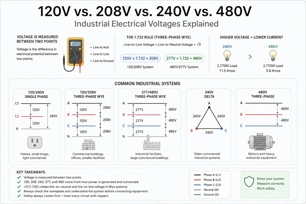
Start With the Most Important Concept: Voltage Is Measured Between Two Points
Saying:
“This wire has 480 volts.”
isn’t quite the complete picture.
Voltage is a difference in electrical potential between two points.
An electrician may measure:
Line to neutral
Line to line
Line to ground
Those measurements can produce different voltages in the same electrical system.
That is one of the biggest reasons apprentices initially find industrial voltage confusing.
A building can legitimately contain:
120V
and
208V
from the same transformer.
Another facility can contain:
277V
and
480V
from the same transformer.
Nothing strange is happening.
The difference comes from which conductors you are measuring between.
The Quick Reference
Here are some of the most common nominal systems in the United States:
Electrical System
Line-to-Neutral
Line-to-Line
Typical Application
120/240V Single Phase
120V
240V
Homes, small shops, light commercial
120/208V Three Phase Wye
120V
208V
Commercial buildings, offices, smaller facilities
277/480V Three Phase Wye
277V
480V
Industrial facilities, large commercial buildings
240V Three Phase Delta
Depends on configuration
240V
Older commercial/industrial systems
480V Three Phase
Depends on configuration
480V
Motors and heavy industrial equipment
The important part is recognizing that 208V and 240V are not interchangeable names for the same system.
We will come back to that.
What Is 120 Volts?
120V is probably the voltage most people in the United States recognize.
Standard receptacles, small appliances, lighting, chargers, power tools, and numerous control circuits commonly operate at approximately 120 volts.
But 120V can come from different electrical systems.
For example:
120/240V Single-Phase System
You can have:
L1 → Neutral = 120V
L2 → Neutral = 120V
L1 → L2 = 240V
This is extremely common in residential electrical service.
But 120V can also come from a three-phase system.
120V From a 208V Three-Phase System
In a 120/208V three-phase Wye system, you typically have three phase conductors:
Phase A
Phase B
Phase C
plus a neutral.
Measure any phase to neutral:
A → N ≈ 120V
B → N ≈ 120V
C → N ≈ 120V
Now measure between phases:
A → B ≈ 208V
B → C ≈ 208V
C → A ≈ 208V
That is why the system is commonly called:
120/208V
or
208Y/120V
The Y represents a Wye connection.
Where Does 208 Volts Come From?
This is where the math becomes interesting.
Many apprentices initially think:
“If one leg is 120 volts and another leg is 120 volts, shouldn’t that equal 240 volts?”
Not necessarily.
In a three-phase Wye system, the phases are electrically separated by 120 degrees.
They are not simply two 120V sources positioned directly opposite each other.
Because of that phase relationship, the line-to-line voltage is:
Line-to-line voltage = Line-to-neutral voltage × √3
The square root of 3 is approximately:
√3 = 1.732
So:
120 × 1.732 = 207.84V
Rounded:
208V
That’s where 208 comes from.
It isn’t an arbitrary electrical-industry number.
It is the mathematical result of a 120V phase-to-neutral voltage in a three-phase Wye system.
The 1.732 Number Every Industrial Electrician Should Recognize
If you work around three-phase systems long enough, 1.732 becomes a familiar number.
For a balanced Wye system:
V Line-to-Line = V Line-to-Neutral × 1.732
And the reverse:
V Line-to-Neutral = V Line-to-Line ÷ 1.732
For example:
120V × 1.732
= approximately 208V
And:
208V ÷ 1.732
= approximately 120V
The same relationship gives us another extremely common industrial voltage pair.
Why 480V and 277V Go Together
Take a 480Y/277V three-phase system.
The voltage between phases is approximately:
480V
But the voltage from one phase to neutral is approximately:
277V
Check the math:
480 ÷ 1.732 = 277.1V
Or going the other direction:
277 × 1.732 ≈ 480V
So a typical 480Y/277V system looks like this:
Phase A → Neutral = 277V
Phase B → Neutral = 277V
Phase C → Neutral = 277V
while:
A → B = 480V
B → C = 480V
C → A = 480V
This is one of the most common power-distribution arrangements in large commercial and industrial facilities.
Industrial electricians are among the many specialized crafts required in these facilities. Næxon’s guide to the highest-paying skilled trades in the oil and gas industry explains how electricians, instrument technicians, millwrights, welders, pipefitters, and other trades fit into major industrial operations.
What Is 277V Normally Used For?
277V is commonly encountered on lighting circuits in larger facilities.
Why use 277V instead of 120V?
For the same amount of power, increasing voltage generally allows the load to operate with less current.
Using the basic relationship:
Power = Voltage × Current
or:
P = V × I
Suppose a load consumes approximately 2,770 watts.
At 277V:
2,770 ÷ 277 = 10 amps
At 120V:
2,770 ÷ 120 ≈ 23.1 amps
The exact engineering of real electrical systems involves additional factors, but the basic principle remains:
Higher voltage can transmit the same amount of power using less current.
That is one reason higher distribution voltages are useful in large facilities.
Why Industrial Plants Use 480 Volts
Now we get into one of the most important voltages for industrial electricians.
480V three-phase power
is extremely common for large equipment such as:
- Motors
- Pumps
- Compressors
- Fans
- Blowers
- Conveyors
- Cooling towers
- Large HVAC equipment
- Process machinery
- Industrial control equipment
- Motor control centers
- Variable-frequency drives
Why 480V?
Again, higher voltage means a given amount of power can be delivered using lower current than would be required at a lower voltage.
For large motors, that matters significantly.
Simple Motor Example: Why Voltage Matters
For a simplified comparison, imagine equipment requiring a substantial amount of electrical power.
Supplying that power at 120V would require far more current than supplying it at 480V.
Higher current generally means:
larger conductors
larger switching equipment
larger overcurrent devices
and
greater voltage-drop concerns
That is one reason heavy industrial equipment is commonly supplied at higher voltages.
You don’t generally power a large process motor from the same type of 120V circuit that feeds the break-room microwave.
208V vs. 240V: One of the Most Common Apprenticeship Confusions
This deserves special attention.
208V is NOT the same as 240V.
Both are common.
Both can supply certain types of equipment.
Both can appear in commercial or industrial facilities.
But they normally come from different system configurations.
Where 240V Comes From in a Typical Single-Phase System
In a standard 120/240V split-phase system, you have two ungrounded conductors positioned approximately 180 electrical degrees apart.
Each measures:
120V to neutral
But because they are opposite each other:
L1 → L2 = 240V
So:
L1 → Neutral = 120V
L2 → Neutral = 120V
L1 → L2 = 240V
This is different from the 120-degree phase relationship in a three-phase Wye system.
Why 120 + 120 Can Equal 240 Here but 208 Somewhere Else
The difference is the phase angle.
In the common 120/240V single-phase split system:
The two legs are approximately 180° apart.
That gives you approximately:
240V line to line
In a 120/208V three-phase Wye system:
The phases are 120° apart.
That produces:
208V line to line
So the difference is not because one building has “weak electricity.”
It comes from how the electrical source is configured.
Think of It This Way
120/240V Single Phase
120V
- ●
120V opposite phase
=
240V line to line
120/208V Three Phase Wye
120V phase-to-neutral
×
√3
=
208V line to line
That difference alone clears up a huge amount of confusion.
Can 240V Equipment Run on 208V?
Sometimes equipment is specifically designed and listed for a range of voltages.
Sometimes it is not.
This is where reading the equipment nameplate becomes critical.
Do not simply assume:
“208 is close enough to 240.”
There is a difference of approximately:
32 volts
That’s about a 13% difference from 240V.
Depending on the equipment, that difference can matter considerably.
Motors, heaters, transformers, contactors, control transformers, and electronic equipment may react differently to incorrect supply voltage.
Always verify:
Nameplate voltage
manufacturer requirements
equipment configuration
and
design documents
before energizing equipment.
Resistive Heating Loads Show the Difference Clearly
Consider a resistive heater designed for 240V.
For a fixed resistance, heating power changes roughly with the square of voltage:
P = V² ÷ R
Reduce the supply voltage and the heater produces less wattage.
That means a heater intended for 240V may produce noticeably less heat when supplied with only 208V, unless it is specifically designed or configured for that voltage.
That’s one reason voltage matters beyond simply asking:
“Will it turn on?”
Motors Have Their Own Voltage Considerations
Motor nameplates can confuse new electricians because the number printed on the motor may not exactly match the nominal facility distribution voltage.
For example, in facilities people commonly refer to:
“480-volt motors.”
But a motor intended for a nominal 480V distribution system may have a nameplate showing something such as:
460V
Similarly, other motor utilization voltages may differ somewhat from the nominal supply-system voltage.
This isn’t automatically a mistake.
Distribution-system voltage and equipment utilization voltage are related concepts, but they are not always represented by exactly the same number.
The rule remains:
Read the nameplate.
Don’t wire equipment based only on what people casually call the system.
What Does “480 Three Phase” Actually Mean?
When someone says:
“That motor is 480 three phase.”
they typically mean the motor receives approximately:
480 volts between phases.
The motor has three phase conductors supplying it.
Conceptually:
Phase A
Phase B
Phase C
Each phase waveform is offset approximately 120 degrees from the others.
That rotating electrical relationship is particularly useful for motors.
Three-phase motors produce a naturally rotating magnetic field, which is one reason three-phase power is so important in industrial facilities.
Why Three-Phase Motors Dominate Industry
Industrial plants contain enormous numbers of three-phase motors.
Walk through a refinery, chemical facility, manufacturing plant, or power station and you’ll find them driving:
Pumps
Fans
compressors
conveyors
blowers
cooling systems
process equipment
Three-phase systems are particularly well suited for efficiently delivering substantial power and operating rotating equipment.
This is one reason electrical and mechanical trades constantly interact in industrial plants.
Millwrights may align the machine.
Pipefitters connect piping to the pump.
Electricians supply the motor.
Instrumentation technicians handle monitoring and control signals.
Operators run the process.
Næxon’s Refinery Turnaround Dictionary covers many of the cross-trade terms workers encounter during industrial shutdowns and maintenance projects.
Wye vs. Delta: Why Configuration Matters
So far, we’ve discussed Wye several times.
But industrial electricians also encounter Delta systems.
Understanding the basic difference is important.
What Is a Wye System?
A Wye connection resembles the letter:
Y
Three transformer windings connect to a common point.
That common connection can provide a:
Neutral
This arrangement allows both line-to-neutral and line-to-line loads.
For a typical:
208Y/120V system
you can obtain:
120V phase to neutral
and
208V phase to phase
For a typical:
480Y/277V system
you can obtain:
277V phase to neutral
and
480V phase to phase
This flexibility makes Wye distribution extremely useful.
What Is a Delta System?
A Delta connection resembles a triangle:
Δ
The windings connect end-to-end.
Basic Delta systems do not have the same neutral point as a Wye connection.
In a Delta system:
Line voltage = phase-winding voltage
So a 240V Delta system can provide approximately:
240V phase to phase.
Industrial electricians may encounter Delta systems in older manufacturing plants, motor applications, and specialized distribution arrangements.
The High-Leg Delta: Pay Attention
One particularly important system is the:
120/240V High-Leg Delta
This system can provide both three-phase power and 120V loads.
But the phase-to-neutral voltages are not all identical.
Typically:
Phase A → Neutral ≈ 120V
Phase C → Neutral ≈ 120V
while the high leg:
Phase B → Neutral ≈ 208V
That conductor is commonly called:
high leg
wild leg
or
stinger
This is exactly why electricians don’t assume every phase-to-neutral measurement will be 120V simply because a neutral exists.
System configuration matters.
And misidentifying a high leg can destroy equipment intended for 120V.
Why the High Leg Measures About 208V
Once again, 208V isn’t appearing randomly.
Geometry and transformer relationships create the voltage.
The center tap providing the neutral is associated with part of the Delta transformer arrangement.
The phase opposite that center point sits farther away electrically from neutral, producing approximately:
208V
from that high leg to neutral.
The important field lesson isn’t memorizing the geometry first.
It’s remembering:
Identify the system before connecting equipment.
Ground Is Not the Same Thing as Neutral
Another important electrical concept:
Neutral and ground are not interchangeable conductors.
They may be bonded together at a designated point in the electrical system, but they perform different functions.
Neutral
Normally carries current as part of the intended circuit when serving line-to-neutral loads.
Equipment Grounding Conductor
Provides a low-impedance fault-current path and bonds equipment together for safety.
Under normal operating conditions, the equipment grounding conductor is not intended to carry continuous load current.
New electricians sometimes see neutral and ground connected at one location and assume they are “basically the same wire.”
They aren’t.
Understanding where and why they are bonded is fundamental to grounding and bonding.
Line-to-Line vs. Line-to-Neutral
This distinction should become automatic.
Line-to-Neutral
Measurement between:
One phase conductor
and
neutral
Examples:
120V on a 208Y/120 system
277V on a 480Y/277 system
Line-to-Line
Measurement between:
Two phase conductors
Examples:
208V
240V
480V
depending on the system.
Line-to-Ground
An electrician may also measure:
Line to ground
In a properly grounded Wye system, line-to-ground voltage will often be close to line-to-neutral voltage.
For example, on a 480Y/277V system:
Phase → Neutral ≈ 277V
and normally:
Phase → Ground ≈ 277V
But that does not mean every electrical system will behave identically.
Delta systems, grounding arrangements, faults, and other conditions can produce very different readings.
Never identify an electrical system from one meter reading alone.
What Should You Expect on a Healthy 208Y/120V System?
A simplified expected set of nominal readings might be:
Phase to Neutral
A-N ≈ 120V
B-N ≈ 120V
C-N ≈ 120V
Phase to Phase
A-B ≈ 208V
B-C ≈ 208V
C-A ≈ 208V
Phase to Ground
A-G ≈ 120V
B-G ≈ 120V
C-G ≈ 120V
Actual measured values can vary somewhat from nominal voltage because of utility supply conditions, transformer settings, voltage drop, loading, and other factors.
What Should You Expect on a Healthy 480Y/277V System?
A simplified set of nominal readings:
Phase to Neutral
A-N ≈ 277V
B-N ≈ 277V
C-N ≈ 277V
Phase to Phase
A-B ≈ 480V
B-C ≈ 480V
C-A ≈ 480V
Phase to Ground
A-G ≈ 277V
B-G ≈ 277V
C-G ≈ 277V
Again, actual readings may differ somewhat from the nominal system designation.
What Does “Nominal Voltage” Mean?
This is another useful term.
When electricians say:
“480 volts”
they are generally describing a nominal system voltage.
That does not mean a digital multimeter must display exactly:
480.000V
every time.
The actual voltage may vary because of:
- Utility conditions
- Transformer taps
- Facility loading
- Conductor voltage drop
- Generator operation
- Distance from source
- System design
- Measurement conditions
Think of nominal voltage as the system’s designated voltage class rather than an expectation that every measurement must hit one exact number.
Why Voltage Drops
Conductors have impedance.
When current flows through a conductor, some voltage is lost between the source and the load.
This is:
Voltage drop.
The basic idea can be represented with Ohm’s law:
V = I × R
More current or greater circuit impedance generally means more voltage drop.
Long conductor runs can therefore create problems if conductors are not properly sized for the application.
This is particularly important on:
temporary power
long construction feeders
motor circuits
industrial equipment
extension cords
and
remote loads
The electrician at the equipment might measure something different from what was measured at the source.
120V Does Not Mean “Safe”
One dangerous misconception is that lower voltage means harmless voltage.
120V can absolutely cause fatal electrical shock.
Higher-voltage systems create additional hazards, but workers should never treat 120V equipment casually.
Electrical injury depends on several factors, including:
current through the body
path through the body
duration of contact
skin condition
environment
and
available fault energy
The number printed on the panel is only part of the hazard.
480V Requires Serious Respect
Industrial workers sometimes become comfortable around 480V because they encounter it every day.
Familiarity should never become complacency.
480V equipment can involve severe:
shock hazards
arc-flash hazards
arc-blast hazards
and
thermal hazards
Industrial switchgear, motor-control centers, disconnects, starters, and distribution equipment may have substantial available fault current.
Work on electrical equipment should follow the facility’s electrical-safety program, lockout/tagout requirements, applicable procedures, equipment labeling, and qualified-person requirements.
General FR workwear should also never automatically be assumed to provide the arc rating required for a particular electrical task.
Næxon discusses this distinction in Your Arms Take More Abuse Than You Think: Why Industrial Workers Wear FR Sleeves, including why electrical PPE must match the actual electrical hazard assessment.
Voltage Is Not the Same Thing as Current
Another common beginner mistake is mixing up:
Volts
and
Amps.
A useful analogy is water pressure and flow.
Voltage is often compared to:
pressure
while current is compared to:
flow rate.
The analogy isn’t perfect, but it helps introduce the concept.
Voltage provides the electrical potential that drives current.
Current is the actual movement of electrical charge through the circuit.
Resistance and impedance oppose that current.
This relationship is represented in basic DC form by:
Ohm’s Law
V = I × R
Where:
V = voltage
I = current
R = resistance
Why Higher Voltage Can Mean Lower Current
From:
P = V × I
we can rearrange:
I = P ÷ V
Suppose a simplified single-phase load requires 4,800 watts.
At 120V:
4,800 ÷ 120 = 40A
At 240V:
4,800 ÷ 240 = 20A
At 480V:
4,800 ÷ 480 = 10A
Real three-phase calculations require the proper three-phase formula and additional factors, but the principle is easy to see:
Increase voltage and the current required for the same power can decrease.
That is a major reason high-power industrial equipment uses higher system voltages.
Three-Phase Power Formula
For balanced three-phase loads, one commonly used real-power relationship is:
P = √3 × V × I × PF
Where:
P = watts
V = line-to-line voltage
I = line current
PF = power factor
The √3 appears again.
For example, a 480V three-phase load drawing 50 amps at a 0.90 power factor would be approximately:
P = 1.732 × 480 × 50 × 0.90
P ≈ 37,400 watts
or approximately:
37.4 kW
Real equipment calculations may require efficiency and other factors depending on what you’re determining.
Why Phase Rotation Matters
Voltage magnitude isn’t the only thing electricians care about with three-phase equipment.
There is also:
Phase sequence.
Common notation includes:
A-B-C
or
L1-L2-L3
Changing the phase sequence can reverse the rotation of many three-phase motors.
That means a motor can have:
the correct voltage
but
the wrong rotation.
A pump rotating backward can fail to perform correctly and may damage equipment depending on the application.
Fans, conveyors, compressors, and other machinery also depend on correct rotation.
Electricians therefore verify more than voltage when commissioning equipment.
What Happens If One Phase Is Lost?
A three-phase motor normally depends on all three phases.
If one phase is lost while the motor is operating, the condition is often called:
single-phasing.
This can cause excessive current in the remaining energized phases, loss of torque, overheating, and motor damage.
Possible causes include:
- Blown fuse
- Open conductor
- Failed contactor pole
- Loose connection
- Damaged cable
- Failed disconnect component
This is why troubleshooting involves checking all phases, not simply confirming that “there’s power.”
What Is Phase Imbalance?
Even when all three phases are present, their voltage levels may not be equal.
For example, suppose measurements show:
A-B = 480V
B-C = 471V
C-A = 483V
That tells the electrician something about the supply or load conditions that deserves investigation.
Three-phase motors generally perform best with a properly balanced supply.
Even relatively small voltage imbalance can contribute to significantly greater current imbalance and motor heating.
For critical rotating equipment, imbalance should never simply be ignored because the motor happens to run.
Voltage at the MCC
In industrial facilities, many motors receive power from a:
Motor Control Center
commonly shortened to:
MCC.
An MCC can contain multiple:
motor starters
circuit breakers
disconnects
contactors
overload devices
control transformers
VFD feeds
and other motor-control components.
A large refinery or manufacturing facility may contain numerous MCCs serving different areas of the plant.
480V three-phase is extremely common in this environment.
This is why industrial electricians need to become comfortable understanding electrical drawings, motor numbers, feeder designations, equipment tags, and voltage classes.
What Does a Control Transformer Do?
Suppose a motor operates at:
480V.
That does not necessarily mean every part of the motor starter’s control system also operates at 480V.
A control transformer can step the voltage down to a lower control voltage.
For example:
480V primary
↓
120V secondary
The motor power circuit may therefore operate at 480V while buttons, coils, relays, or other portions of the control system operate at a different voltage.
Modern systems may also use other control voltages such as 24VDC.
Understanding power circuits vs. control circuits is another major step in industrial electrical training.
What Is a VFD?
A:
Variable Frequency Drive
or
VFD
controls an AC motor by changing the electrical frequency and voltage supplied to the motor.
Instead of simply:
OFF
or
full speed
a VFD allows controlled motor operation across a range of speeds.
Industrial facilities use VFDs extensively on:
pumps
fans
conveyors
blowers
and many process applications.
The incoming side of a VFD may receive 480V three-phase power, while the output waveform supplied to the motor is electronically controlled by the drive.
That means troubleshooting VFD-driven motors requires understanding more than ordinary line-voltage measurements.
Don’t Assume Wire Color Tells You Everything
Electricians often work with established color conventions.
But color alone should never be treated as proof of voltage.
Facilities differ.
Old installations differ from new construction.
Previous workers make mistakes.
Conductors get reidentified.
Control wiring can be complex.
Temporary power can be especially confusing.
A qualified electrician identifies the circuit using:
drawings
labels
equipment information
approved test instruments
and
safe electrical work practices.
Never trust a conductor solely because:
“It’s the color we normally use for 480.”
Read the Nameplate Before Connecting Anything
Equipment nameplates are one of the best sources of information an electrician has.
A motor nameplate may show:
Voltage
Phase
Frequency
Full-load current
Horsepower
RPM
Service factor
Insulation class
NEMA design information
and other important details.
Before energizing equipment, make sure the supply matches the equipment requirements.
Do not let:
“It physically plugs in”
or
“The wires fit”
become the electrical equivalent of engineering.
60 Hertz: Another Number You Will See Everywhere
In the United States, most standard AC power systems operate at approximately:
60 Hz
or 60 cycles per second.
Frequency influences the operation and speed of AC motors.
For example, synchronous speed can be calculated using:
Synchronous RPM = (120 × Frequency) ÷ Number of Poles
A four-pole motor supplied at 60 Hz has a synchronous speed of:
(120 × 60) ÷ 4 = 1,800 RPM
An induction motor will typically operate somewhat below synchronous speed because of:
slip.
This is why you commonly see motor nameplate speeds such as approximately:
1,750 RPM
rather than exactly:
1,800 RPM
depending on the motor and load.
Quick Voltage Memory Guide
If you are learning industrial electrical systems, remember these combinations:
120/240V Single Phase
120V line to neutral
240V line to line
Common in residential and lighter commercial applications.
208Y/120V Three Phase
120V line to neutral
208V line to line
Very common in commercial facilities.
Remember:
120 × 1.732 ≈ 208
480Y/277V Three Phase
277V line to neutral
480V line to line
Extremely common in industrial and large commercial facilities.
Remember:
277 × 1.732 ≈ 480
240V Delta
Typically:
240V line to line
but the phase-to-neutral behavior depends on the specific Delta configuration.
Don’t assume it behaves like a Wye system.
208V vs. 240V vs. 480V at a Glance
Voltage
Where It Commonly Comes From
Common Uses
120V
Line-neutral on 120/208 Wye or 120/240 split phase
Receptacles, lighting, controls
208V
Line-line on 120/208 Wye
Commercial equipment, small motors, HVAC
240V
Line-line split phase or Delta system
Heaters, equipment, motors
277V
Line-neutral on 480/277 Wye
Commercial/industrial lighting
480V
Line-line on industrial three-phase systems
Motors, MCCs, large equipment
Common Apprentice Mistakes
“Two 120V phases always make 240V.”
False.
In a 208Y/120 three-phase system, two phases measure approximately 208V because the phases are separated by 120 electrical degrees.
“208 and 240 are basically the same.”
False.
They are different nominal voltages.
Equipment compatibility must be verified.
“A 480V system has 480 volts from every phase to ground.”
Not on a typical 480Y/277V Wye system.
You normally expect approximately 277V phase to neutral and phase to ground, with 480V phase to phase.
“Neutral and ground are the same thing.”
False.
They have different functions even though they are intentionally bonded at designated points in the system.
“If the motor runs, the wiring must be correct.”
False.
It may have incorrect rotation, voltage imbalance, improper voltage, incorrect protection, or another issue.
“120V isn’t dangerous.”
Very false.
Potentially fatal shock can occur at 120V.
The Field Rule: Ask What You’re Measuring Between
Whenever someone gives you a voltage number, train yourself to ask mentally:
Between what two points?
Phase to phase?
Phase to neutral?
Phase to ground?
Neutral to ground?
That question prevents a huge amount of confusion.
Because:
120V and 208V can exist in the same panel.
277V and 480V can exist in the same panel.
The number changes depending on where you measure.
How to Remember the Entire System
Here is the easiest mental shortcut:
120 ↔ 208
Think:
120 × 1.732 = 208
Three-phase Wye.
277 ↔ 480
Think:
277 × 1.732 = 480
Three-phase Wye.
120 ↔ 240
Think:
Split phase.
Two 120V legs approximately 180° apart.
Industrial Electricity Makes More Sense Once the Numbers Connect
At first, electrical voltages can seem like a collection of unrelated numbers:
- 120.
- 121.
- 122.
- 123.
- 124.
But once you understand the source, the pattern becomes clear.
120/208 belongs naturally together in a three-phase Wye system.
277/480 belongs naturally together in a three-phase Wye system.
120/240 belongs naturally together in the common split-phase system.
And 1.732—the square root of three—is the mathematical bridge between line-to-neutral and line-to-line voltage in a balanced three-phase Wye system.
For an industrial electrician, that understanding is much more valuable than simply memorizing voltage numbers.
Because the goal isn’t merely knowing that a panel says 480V.
The goal is being able to look at the system and understand:
where that 480V comes from, what you should expect between conductors, what equipment it is serving, and why the system was designed that way.
That’s the difference between memorizing electrical terminology and actually beginning to understand industrial power distribution.
Continue exploring practical knowledge for electricians, instrumentation technicians, millwrights, ironworkers, welders, boilermakers, riggers, operators, and the rest of the industrial workforce in the Næxon Learning Center.


